
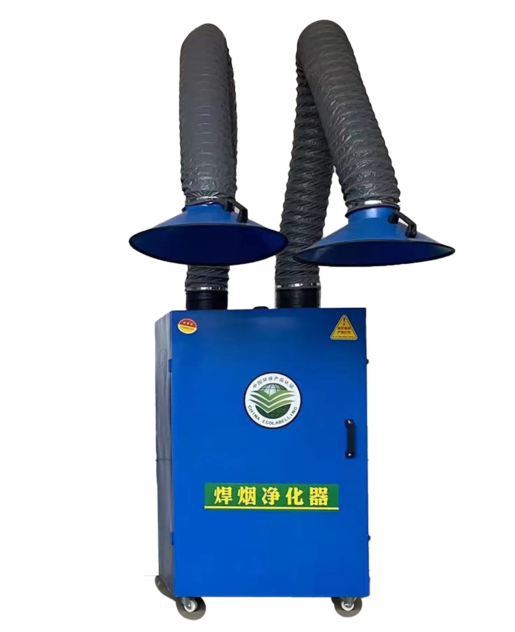
Welding fume extraction arm selection starts with the weld path and required capture, then checks the hood, hose, fan, filters and discharge as one system. Reach and a filter-efficiency percentage are not enough. The arm must hold an effective hood position throughout the task, and the fan must maintain the agreed duty with the installed hose and loaded filters.
This technical guide focuses on evaluating a working station and preparing an acceptance record. Published HYC model figures below are supplier reference data, not independently verified field results. Worked calculations are explicitly assumed and do not establish a safe operating setting.
1. Define welding fumes and the station before choosing an arm
Record the welding process, base metal, coatings, consumables, current range, weld length, duty cycle and number of simultaneous operators. Fume composition varies with these inputs. Welding can also generate gases, so particle filtration does not address every contaminant. Avoid assuming that every weld contains chromium(VI), or that a low visible-fume process needs no controls.
Map the operator, workpiece, start and finish of each weld, screens, doors and other sources of cross-draught. The hood should intercept the plume without drawing it across the breathing zone. Check whether the arm can reach both ends of the work while remaining stable and leaving the operator a usable line of sight. A long arm that drifts or is difficult to move may not remain in its intended position.
Separate three acceptance questions: does the hood capture the contaminant, does the filter treat the captured stream, and is the discharge arrangement suitable? Neither a particle-filter percentage nor a clean-looking outlet establishes workplace exposure control. Where LEV does not adequately control exposure, further assessed controls, including suitable RPE where required, remain necessary.
For US general-industry work within its scope, OSHA 1910.1026 sets a chromium(VI) permissible exposure limit of 5 µg/m³ as an eight-hour time-weighted average. This is a substance- and jurisdiction-specific exposure limit, not a universal welding-fume limit or collector outlet specification.
2. Evaluate extraction arm capture distance and installed airflow
Do not select a universal hood-to-weld distance from the arm diameter. Hood geometry, source momentum, plume direction, surrounding obstructions and draughts change capture. Establish the permitted position and working range during commissioning and make that arrangement understandable to the operator. Reposition the hood as the weld moves rather than relying on arm reach alone.
HSE welding-extraction testing guidance describes comparison with 0.5–1.0 m/s capture velocity for appropriate LEV tests, with higher values potentially needed under interfering draughts. It explicitly excludes this capture-velocity test for on-torch extraction, where volumetric flow is compared with manufacturer recommendations. Effective fume capture must also be assessed; an isolated velocity reading is insufficient.
Keep hose velocity separate from capture velocity
Assume 1,500 m³/h passes through a circular hose with a true 160 mm internal diameter. Q=1,500÷3,600=0.4167 m³/s; area=π×0.160²÷4=0.020106 m²; average internal velocity=Q/area=20.72 m/s. This is a continuity calculation inside the hose, not a velocity at the weld.
| Assumed internal bore | Area | Velocity at assumed 1,500 m³/h |
|---|---|---|
| 140 mm | 0.015394 m² | 27.07 m/s |
| 160 mm | 0.020106 m² | 20.72 m/s |
| 180 mm | 0.025447 m² | 16.37 m/s |
All three rows hold flow artificially constant to isolate the geometry effect. A real fan may deliver a different flow when hose diameter, length or bends change. Corrugation and fittings add resistance. Request a fan duty that includes the offered arm, adapters, filters and discharge route rather than extrapolating from this table.
Define simultaneous operation for two arms
An assumed allocation of 1,500 m³/h to each of two arms totals 3,000 m³/h. That sum is not proof that both branches receive their allocation. Measure each branch with both open, then examine the approved single-arm state. A shared fan, damper change or unequal hose length can redistribute flow. Specify the permitted configurations and controls.
3. Compare HYC configurations without confusing ratings
The supplier-published HYC schedule lists the following model identifiers and nominal airflow/power figures. Preserve the distinction between these references and a confirmed installed duty. A model number is not a fan curve, and a motor rating does not establish airflow at resistance.
| Published model | Listed airflow(m³/h) | Listed motor(kW) |
|---|---|---|
| HYC-1500 | 1,000–1,500 | 1.1 |
| HYC-3000 | 2,000–3,000 | 2.2 |
| HYC-3000 Pro | 3,000–4,000 | 3.0 |
| HYC-5000 | 4,000–5,000 | 4.0 |
| HYC-6000 | 5,000–6,000 | 5.5 |
| HYC-7000 | 6,000–7,000 | 7.5 |
| HYC-Dual 1000 | 1,000×2; confirm branch basis | 2.2 |
| HYC-Dual 3000 | 3,000×2; confirm branch basis | 5.0 |
| HYC-Mobility | 1,500 | 1.1 |
| HYC-IndustrialPro | 7,000 | 7.5 |
Use the welding fume purifier configuration page as a starting point and obtain a signed schedule for the offered unit. Confirm supply voltage, phase, frequency, installed weight, hose bore, arm reach, fan curve and service access. The published schedule uses different efficiency expressions, including>95%,99.7% at 0.3 µm and 99.97%; these are not interchangeable evidence of hood capture or complete-system performance.
Ask for the tested model, filter stages, aerosol, particle-size basis, standard, airflow and specimen boundary. Distinguish a media test from a complete-element or assembled-unit test. Similarly, supplier temperature and noise figures need measurement locations, duration and test conditions. Do not turn a listed cartridge life into a guaranteed replacement interval.
4. Specify filtration, discharge and safe servicing
A typical configuration can include an inlet spatter screen, primary cartridge and optional final filter. Identify the actual supplied sequence. An inlet mesh may intercept some spatter; it is not proof of complete spark elimination, fire prevention or explosion protection. Grinding dust requires a separate assessment and should not be mixed into a welding-fume system merely because a hose fits.
A particulate filter does not remove all welding gases. If carbon adsorption is proposed, identify the target compounds, expected loading, humidity, contact conditions and breakthrough or replacement criterion. Odour disappearance is not a complete performance test. Filtered-air recirculation requires a contaminant-specific and jurisdiction-specific assessment; an H13 label alone does not approve it.
ISO 21904-1:2020 covers general requirements for welding-fume capture and separation equipment, including mobile and stationary equipment. Its official scope excludes grinding dust, general ventilation and certain other hazards. The standard is published and marked for revision; request the applicable part and edition when ordering. A reference to the series is not evidence that a particular HYC model conforms.
Plan access for filter changes, containment of collected material, disposal, isolation of electrical and stored pneumatic energy, and checks before restart. Management-system certificates address the organization's systems; they do not substitute for model-specific conformity, filter performance or application approval.
5. Commission the station and record repeatable conditions
Agree the workpiece and welding conditions used for the trial before delivery. Test the hood at the furthest approved positions, with representative cross-draughts and simultaneous stations. Observe capture safely using appropriate eye protection and assessment methods, then document the airflow and pressure measurements that describe that accepted configuration.
| Acceptance item | Record required |
|---|---|
| Hood and arm | Position range, reach, stability, operator access and repositioning instructions |
| Air system | Actual flow, test method, pressure boundaries, hose layout and open branches |
| Filtration | Exact element identification, resistance state, cleaning settings and outlet evidence |
| Exposure and discharge | Competent assessment against applicable requirements, including gases |
| Maintenance | Inspection access, isolation procedure, consumables and waste handling |
Establish what changes trigger reassessment: new consumables, longer hose, another station, moved screens, a different final filter or altered discharge. Routine checks should compare like-for-like operating states. Low filter differential pressure can accompany low airflow or leakage and is not proof of satisfactory capture.
For moving jobs, use the separate portable collector deployment guide to assess travel routes and utilities. Send the station layout, process information and acceptance requirements through SENOTAY project enquiries; include missing test evidence as an open item in the quotation.
Key takeaways
Select the hood and arm around the actual weld path and capture conditions.
Keep internal hose velocity, capture velocity and filter efficiency distinct.
Confirm simultaneous-branch duty with the installed resistance and filter stages.
Use model-specific evidence and an agreed commissioning record, not a generic percentage.
6. Frequently asked questions
How close should an extraction arm be to the weld?
Use the position and working range established for the hood, process and surrounding conditions during commissioning. Arm reach alone does not define an effective capture distance; reposition the hood as the weld moves.
Does 20.7 m/s in a hose prove effective capture?
No. That is the average internal velocity for the stated assumed flow and 160 mm bore. Velocity at the weld and actual capture depend on the hood, distance, plume and draughts.
Can two arms share one purifier?
Yes, if the proposed system is approved for the simultaneous duty. Confirm airflow at each arm, loaded-filter resistance, permitted damper states and the fan operating point.
Can a welding purifier also collect grinding dust?
Do not assume so. Grinding changes the dust and ignition hazards and is outside ISO 21904-1’s stated scope. Obtain a separate application assessment and configuration approval.