
EN
What are you looking for?
A mineral mill needed to reduce abrasive solids reaching its existing baghouse. This representative Combined Cyclone Dust Collector application examines a 5,000 m³/h extraction duty, an 80% pre-separation target and the measurements needed to verify downstream benefits.
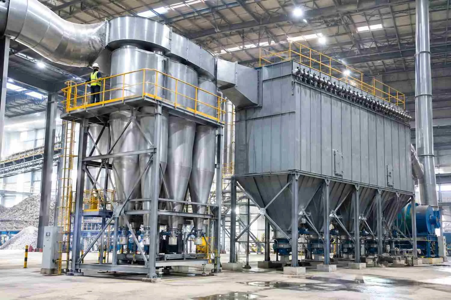
A combined cyclone removes a proportion of the incoming dust before the remaining gas reaches the baghouse. Multiple cyclone elements may operate in parallel; the cyclone and baghouse then form successive treatment stages. In this illustrative mineral-mill case, an 80% pre-separation target reduces assumed baghouse inlet loading from 50 to 10 kg/h. The downstream filter remains responsible for final fine-particle control.
All comparisons below are illustrative. The baseline period is 1–7 June 2026; the proposed comparison period is 1–7 July 2026.
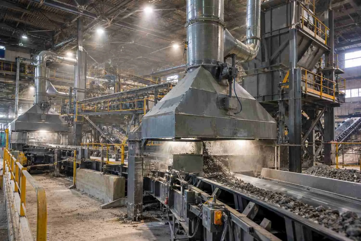
The representative plant milled and screened a dry, noncombustible mineral product before transferring it to storage. Dust extraction served enclosed transfer points and a screening station. The assumed duty was 5,000 actual m³/h at 40 °C, with pollutant loading changing as feed conditions varied.
Maintenance staff faced abrasion and repeated attention to the baghouse’s dirty side. The production manager wanted fewer dust-related interruptions, while the environmental manager needed reliable stack evidence. The engineering task was to reduce the incoming solids burden without weakening capture at the source or treating the existing filter as expendable.
The existing baghouse received the full extracted dust stream. In the representative operating history, changing feed conditions produced periods of heavier solids loading, more cleaning activity and additional inspection work.
The plant first checked compressed-air delivery and adjusted the cleaning sequence. That addressed one possible cause of rising resistance, but it did not remove abrasive particles before they reached the collector. Increasing cleaning intensity also could not repair damaged inlet protection or establish whether the hopper emptied reliably.
Continuing unchanged meant accepting uncertain maintenance demand and recurring dust-related interruptions. Yet adding equipment created its own risk: extra resistance could reduce airflow at the transfer enclosures.
The plant therefore needed a defensible relationship between particle size, captured mass and fan duty. Available floor space was restricted, and the discharge arrangement had to fit the existing solids-handling route.
A cyclone uses swirling gas motion to separate particles by inertia. Larger or denser particles tend to move toward the outer wall while gas changes direction and exits through the outlet. Collected solids must then leave the hopper without being drawn back into the gas stream.
EPA describes cyclones as common pre-cleaners for larger, abrasive particles and explains that multicyclones combine smaller separating elements in parallel. Performance depends on the inlet particle-size distribution. See EPA’s cyclone operating guidance.
Parallel operation divides the incoming flow among elements. Each element handles a share of the gas; the same gas does not automatically pass through every cyclone. Successive treatment stages arise here because the combined separator discharges to the retained baghouse.
Grade efficiency is collection efficiency for a specified particle-size interval. Overall efficiency combines the different size fractions according to their contribution to inlet mass. A stream dominated by coarse particles can therefore show strong mass removal while a substantial fine fraction remains airborne.
Pre-separation changes the material entering the baghouse. The remaining dust may contain a greater proportion of fine particles, so lower total loading does not automatically produce a proportional reduction in pressure loss, pulse demand or emissions.
The practical lesson is to measure both the quantity and character of the residual dust.
The representative specification used separate acceptance criteria for the cyclone stage and final exhaust. Meeting the pre-separation target would not excuse a failed stack test. The owner would also need to identify the applicable environmental permit before assigning a legal emission limit; the values below are contractual assumptions.
The alternatives address different causes of baghouse difficulty.
Repair wins when the existing system’s problems originate in damaged internals or blocked discharge. A settling chamber deserves consideration where space is available and the dust is predominantly coarse. A combined arrangement becomes more attractive when the required flow and separation duty justify multiple elements. It is the wrong answer when the troublesome material is predominantly fine, sticky or wet and the proposed geometry cannot handle that condition. Obtain a size-resolved performance basis before selecting it.
No customer purchase record was supplied. In this scenario, the buyer would require a signed flow and particle-size envelope, a pressure-loss curve and a drawing that distinguishes cyclone-only separation from any integrated filter stage. That distinction matters because a package efficiency cannot be assigned to its cyclone elements without separate evidence.
For this representative design, we selected the CC-5000 designation listed on Senotay’s Combined Cyclone Dust Collector page. The proposed scope is a cyclone pre-separator upstream of the existing baghouse; the catalogue does not establish the exact internal arrangement, so a signed drawing is a procurement hold point.
The representative configuration included:
A 304 collecting body, with wall thickness established by structural and wear calculations.
Parallel separating elements and distribution plenums sized for the agreed duty.
Accessible wear zones and removable inspection covers.
A sealed hopper outlet and rotary discharge arrangement.
Pressure connections, sampling access and integration with the retained extraction system.
We chose an 80% mass-removal target → over a universal fine-particle efficiency claim → because the assumed 50 kg/h inlet burden offered a useful 40 kg/h diversion before the baghouse. The guarantee would specify the particle-size distribution supporting that target.
We chose a 1,200 Pa pressure allowance → over assuming pre-separation saves fan energy → because additional resistance at 5,000 m³/h requires an explicit fan check.
We chose sealed discharge rated against the 40 kg/h captured-load example → over an intermittently opened hopper → because solids removal must not introduce uncontrolled air leakage. Final discharge sizing would include peak loading, bulk density and operating margin.
The model name anchors the enquiry, not a complete construction specification. Element count, geometry, wear protection, connections, supports and discharge equipment require project approval. The trade-off is additional resistance and inspection scope in exchange for a potential reduction in downstream solids burden. No filter-life extension or energy saving is guaranteed by this representative selection.
The following route is proposed rather than recorded project history. Senotay’s factory informationprovides company context; it does not verify this build’s machinery, tolerances or inspection results.
Fabrication would begin with traceable 304 sheet, followed by cutting and forming of cylinders, cones and connecting sections. Cutting equipment must accommodate the approved plate thickness; forming equipment must produce the specified geometry without relying on forced fit during assembly.
The fabricator would join the shells, assemble the outlet tubes and inspect internal transitions. The representative alignment target is ±2 mm for outlet-tube position against the approved drawing, verified with calibrated dimensional tools. This is an assumed project tolerance, not a published CC-5000 specification.
Surface preparation would remove fabrication contamination before final assembly. The hopper, access covers, seals and discharge interface would then undergo dimensional and functional checks.
The illustrative 7-week programme allocates 2 weeks to engineering and procurement, 3 weeks to fabrication, 1 week to assembly and inspection, and 1 week to packing. The anticipated difficult task is maintaining consistent geometry across the elements. The actual hardest operation, number of attempts and rework history remain unknown; production records must supply them.
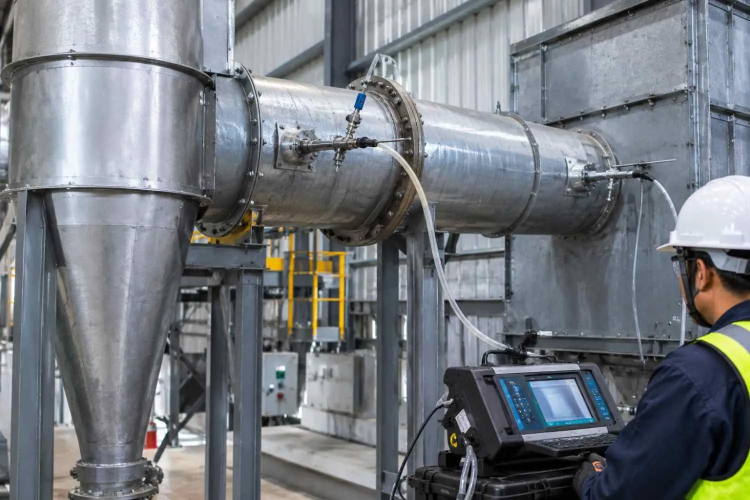
EPA Method 5determines particulate mass using isokinetic extraction and gravimetric analysis. It specifies a filter temperature of 120 ±14 °C unless another approved requirement applies. It does not establish a universal 10 mg/Nm³ limit or measure every possible condensable fraction.
An independent testing organization would assess method applicability and sample the cyclone inlet, cyclone outlet and final stack under agreed conditions. The representative plan uses 3 runs of 60 minutes; that duration is a project assumption, not a universal Method 5 requirement. Stage efficiency uses mass flows, while stack acceptance uses the agreed dry reference basis.
A failed contractual test requires investigation, correction and retesting. Legal consequences depend on the applicable permit. Senotay’s quality-control informationdoes not replace project-specific evidence.
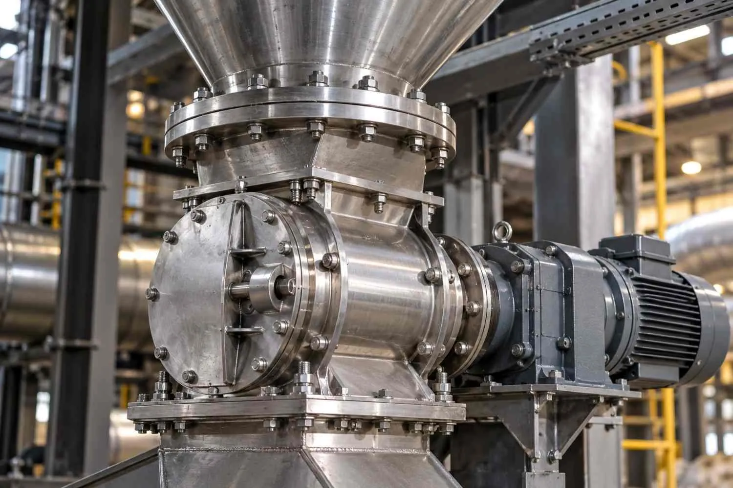
The illustrative startup problem was air entering through an inadequately sealed hopper connection. Gas flow appeared acceptable at the main duct, but the discharge arrangement disrupted stable operation. The team corrected the seal and repeated the pressure and flow checks before assessing separation. This is a representative event, not a recorded site incident.
Commissioning would confirm source capture, fan duty, discharge operation and stable differential pressure.
Handover would include isolation instructions, drawings, seal inspection points, discharge maintenance, instrument checks and spare-part identification. Training would emphasize that an empty hopper does not prove effective collection; it can also indicate poor separation or an obstructed dust path.
The scenario compares 1–7 June 2026 with 1–7 July 2026. These are illustrative dates and values, not field records.
The loading reduction is calculated as (50 − 10) ÷ 50 × 100 = 80%. Actual verification would need comparable inlet loading, production rate and particle-size distribution, plus an assessment of air leakage.
The unexpected benefit in the scenario is easier examination of the separated coarse fraction. That material could help maintenance identify changing feed conditions or unusual wear debris.
The condition that does not improve is system resistance. Added pressure loss consumes fan capability and may increase electricity demand. Commercial evaluation must therefore compare confirmed maintenance and production benefits with power, discharge equipment, wear parts and capital cost. Without installed pricing and operating records, neither payback nor additional bag life can be calculated honestly.
"Installing the CC-5000 pre-separator gives us a clear path to reduce the abrasive dust load on our existing baghouse, but we'll need to verify actual stage efficiency and pressure loss against our varying feed conditions before committing to full-scale rollout."
— Mr.Liu , Plant Operations Manager, Jiangsu Mineral-Milling Plant.
A cyclone proposal should show where the dust mass goes. Use gas flow and concentration on the same temperature, pressure and moisture basis; mixing actual wet flow with dry normalized concentration produces an invalid mass balance.
Dust mass flow, kg/h = gas flow, m³/h × concentration, g/m³ ÷ 1,000.
For the assumed 5,000 actual m³/h and 10 g/actual m³ inlet concentration:
Inlet dust = 5,000 × 10 ÷ 1,000 = 50 kg/h.
At an assumed 80% cyclone-stage efficiency:
Captured dust = 50 × 0.80 = 40 kg/h.
Dust reaching the baghouse = 50 − 40 = 10 kg/h.
These are derived from representative inputs, not measurements. With negligible leakage and unchanged gas conditions, the corresponding residual concentration is 2 g/actual m³.
Overall efficiency = 1 − [(1 − cyclone efficiency) × (1 − downstream efficiency)].
Use efficiencies as decimal fractions. An assumed 80% cyclone stage followed by a baghouse capturing 99% of its own inlet mass gives:
1 − [(1 − 0.80) × (1 − 0.99)] = 0.998 = 99.8%.
Residual mass is 50 × 0.002 = 0.10 kg/h. At unchanged actual flow, that equals 20 mg/actual m³—not proof of meeting a dry-normalized 10 mg/Nm³ target. More stages do not remove the need for a final outlet guarantee.
Provide maximum actual airflow, representative particle-size distribution and density, peak dust loading, and temperature/moisture conditions. Ask suppliers for grade-efficiency evidence, pressure loss across the operating range, internal configuration and discharge capacity.
Trend operating measurements against the conditions recorded during acceptance. A different dust distribution can change capture even if fan speed stays constant.
Inspect under the approved isolation procedure. Record wear at repeatable locations so successive readings show change rather than differences in measurement position. A cyclone body may have no driven internals, but its rotary valve, fan and solids-handling equipment still require maintenance. Do not reset a discharge fault without checking accumulated material and the consequences for upstream extraction.
Senotay lists these models and nominal power values. The table does not establish what loads the quoted power includes; confirm the supplied fan and auxiliaries separately.
The selected designation is CC-5000. Confirm element geometry, material thickness, integrated-filter scope and power allocation before ordering. The full model-specific specification remains unresolved; this configuration is one of 10 in the range.
Ans: No. The target refers to total inlet dust mass under an agreed size distribution. Collection varies by particle size and other properties. A change toward finer material can reduce overall performance even when flow remains unchanged. Request a grade-efficiency curve or relevant test data, not only a single percentage.
Ans: Not on the evidence available here. The representative design retains the baghouse for residual fine-particle control. Removing it would require a separate demonstration that the cyclone alone meets the applicable outlet requirements throughout the operating envelope. The assumed pre-separation target does not establish that capability.
Ans: Possibly, but the extension cannot be predicted from removed mass alone. Bag wear also depends on inlet distribution, media selection, chemistry, moisture and cleaning. Record failures and operating conditions over a meaningful period before attributing additional life to the retrofit or including it in a savings calculation.
Ans: No. More parallel elements mainly change the way flow is shared. Their diameter, individual flow, geometry and distribution determine the resulting performance. Operating elements outside their intended range can undermine separation. Ask for the actual arrangement and operating envelope rather than treating element count as an efficiency guarantee.
Ans: Include the separator, supports, discharge equipment, duct changes, instruments, fan assessment and acceptance testing. Ask which exclusions affect performance and who owns integration with the existing baghouse. Compare operating costs as well as purchase price; the representative case does not establish that a higher catalogue power means higher measured consumption.
For an initial review, send airflow, dust loading and particle-size results. For a quotation, add drawings, fan information and the final outlet requirement through Senotay’s enquiry page. Request an initial scope response within 2 working days; supplier agreement is required.
Related resources:
Single-cylinder cyclone: compare a simpler separating arrangement.
Baghouse equipment: review the downstream filtration role.
Senotay application cases: request a verified mineral-processing installation and a combined-cyclone reference from another industry.