
EN
What are you looking for?

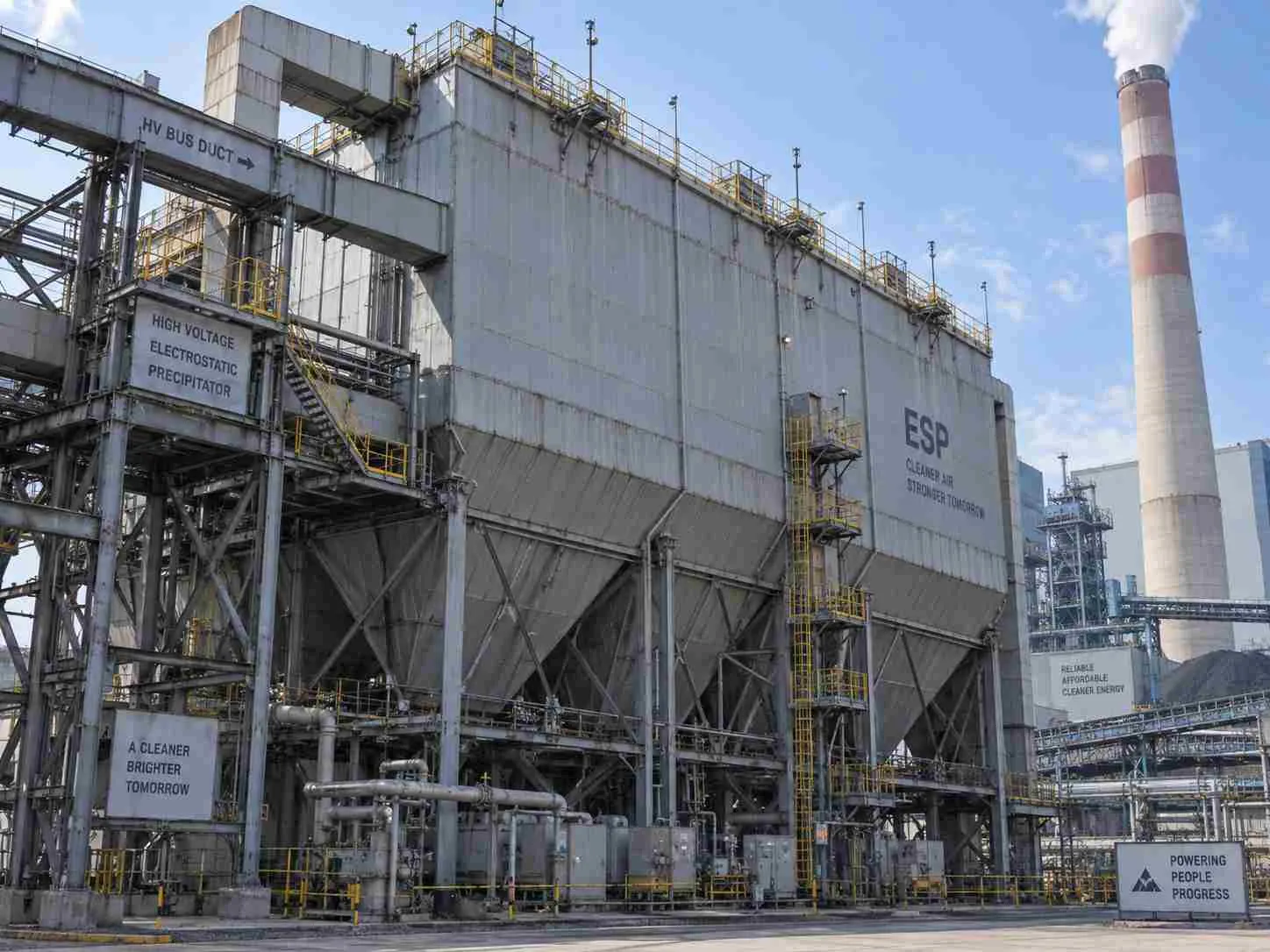
A coal-fired power station needed dependable fly-ash capture without excessive draft loss. This representative Horizontal Electrostatic Precipitator review examines HESP-200 selection, an illustrative 45-to-18 mg/Nm³ outlet improvement, and the tests needed to establish actual performance.
Project facts and specification basis
The panel separates the selected catalogue model from the assumed deployment.
A horizontal electrostatic precipitator removes fly ash by electrically charging particles and collecting them on plates. Power-plant performance depends on actual gas flow, collecting area, ash resistivity, electrical conditions and rapping control. This representative HESP-200 review uses a 30 mg/Nm³ contractual outlet target. The target and illustrative results require project testing; a catalogue efficiency percentage alone cannot demonstrate compliance.
June and August 2026 are illustrative comparison months. The evidence column identifies required records, not records already supplied.
The representative station operated a 20 MW generating unit on a continuous schedule. The boiler supervisor needed a stable draft, the electrical maintenance team maintained high-voltage equipment, and the environmental manager had responsibility for defensible particulate records.
Fly ash characteristics changed with the fuel blend, while gas volume varied with load and air leakage. The collector therefore had to perform across operating conditions rather than only at a convenient test point. Operators also needed uninterrupted ash evacuation: material retained in a hopper could compromise the electrical equipment above it.
The representative plant experienced intermittent outlet dust peaks during load transitions and ash removal. Electrical trips became harder to interpret because operating records did not align field current, rapper activity and boiler load on a common timeline.
Maintenance increased rapping frequency and cleaned accessible insulators. Operators also adjusted power settings. These measures temporarily changed the symptoms, but dust peaks returned because the team had not established whether uneven flow, ash properties or an electrical clearance problem was dominant.
More rapping could release collected ash back into the gas stream. More voltage could increase sparking where an electrode was misaligned. Neither intervention guaranteed better particulate capture.
Doing nothing meant recurring troubleshooting, operating interruptions and uncertainty over the emissions trend. The existing duct centreline and ash-conveyor route constrained the replacement arrangement. The project had to preserve draft capability while fitting electrical access and maintenance clearances around those interfaces, without assuming that the existing foundations could carry new loads.
Electrostatic collection works by charging particles, moving them to plates and removing the deposited ash without losing it back into the gas stream.
Corona discharge is localized ionization near an energized electrode. Ash resistivity is the material property describing resistance to electrical conduction. Re-entrainment is the return of collected particles to the flowing gas.
In a typical negative-corona dry ESP, discharge electrodes create ions that charge passing particles. The electric field moves charged particles toward grounded collecting plates. Mechanical rapping then releases deposits into hoppers.
Ash must retain enough charge to remain collected while allowing charge to dissipate through the deposit. The EPA’s ESP monitoring guidance identifies resistivity, electrical readings, gas flow and rapper operation as important performance factors.
A highly resistive deposit can support electrical breakdown within the ash layer, reducing useful collection. Very conductive ash can lose its holding charge quickly and become easier to re-entrain. Fuel and temperature records therefore belong beside the electrical trends.
A high-velocity lane gives particles less time to reach a collecting surface. Other lanes may be underused even though total airflow looks acceptable. Improving distribution can therefore matter more than raising a single power setting. Diagnose the process across the inlet, collecting fields and discharge system rather than treating each alarm independently.
The representative acceptance target is 30 mg/Nm³ of outlet particulate on a specified dry reference basis. It is a contractual assumption, not a claim about the legal limit at an unidentified station. Applicable permit limits, oxygen correction and operating conditions must be established before a compliance statement is issued.
Requirements distinguish non-negotiable duty from operating preferences.
Repair is preferable when the existing equipment can meet the duty after identifiable faults are corrected.
The options compare realistic routes for this application.
A dry ESP is the wrong answer when ash behaviour, condensation or the available footprint defeats the required duty. A fabric filter may be more defensible for difficult resistivity, provided temperature and chemistry suit its media. Wet polishing is not interchangeable with a primary dry fly-ash collector.
No procurement record confirms why a customer selected Senotay. In this scenario, the evaluation required a gas-distribution assessment, ash-characterization results and an outlet guarantee tied to actual operating conditions.
A supplier would need to explain the collection-area calculation and show how electrical sections, ash discharge and access fit the approved arrangement. A generic efficiency label would not settle those questions.
In the representative supply narrative, we supplied one Senotay HESP-200 dry electrostatic precipitator. The published model lists 120,000 m³/h gas capacity and 2,500 m² collecting area; order-specific engineering remains necessary.
The proposed configuration comprised:
Three independently energized electrical fields in series.
Q235B casing and collecting plates, subject to structural approval.
Type 304 discharge electrodes, subject to corrosion and mechanical review.
Transformer-rectifier supplies with field-level operating trends.
Sequenced mechanical rapping and hopper-level monitoring.
Continuous ash discharge, heated insulator compartments and access interlocks.
These are representative selections, not confirmed standard inclusions.
We chose → inlet distribution correction over → voltage escalation alone because → 120,000 m³/h had to use the full collecting cross-section. The design review needed to identify fast lanes and bypass paths, then verify the installed arrangement.
We chose → 3 independently controlled fields over → one common electrical section because → a localized fault should not automatically remove energization from every field. Remaining fields would not necessarily maintain the guaranteed outlet limit; the operating procedure needed to state the response to a trip.
We chose → sequenced rapping over → simultaneous rapping because → the proposed 30 mg/Nm³ target required control of transient re-entrainment. Operators would compare particulate traces with each rapper sequence before accepting settings.
The catalogue model defined the starting point. Material grades, field arrangement, supports, power supplies and controls required approved drawings. The accepted trade-off was additional electrical maintenance: eliminating filter bags does not eliminate electrode, insulator or rapper inspections.
The build route below is a representative manufacturing account. Senotay’s factory capability page provides supplier context, not proof that these events occurred on a specific order.
We checked material certificates, cut Q235B panels and formed the hopper and collecting components. The proposed casing thickness was 6 mm, subject to pressure, wind, seismic and support calculations. Cutting and forming equipment needed demonstrated capacity for the approved panel dimensions; machine tonnage was not available for verification.
We assembled the casing in a controlled weld sequence, installed supports, and checked electrode alignment before completing the internal assembly. A representative ±3 mm positioning allowance relative to the approved electrode datum was checked with calibrated gauges and a dimensional survey. The final electrical clearance required its own drawing limit.
A representative support bracket moved after welding. We corrected the bracket and repeated the alignment survey; the second check met the proposed positioning allowance. Actual inspection records must replace this illustrative event.
We then applied the approved external coating system, assembled insulators and rappers, checked continuity and protected components for shipment. Internal coatings required electrical-design approval rather than automatic use.
The proposed 12-week programme comprised 3 weeks engineering, 5 weeks fabrication, 2 weeks assembly/testing and 2 weeks packing/release. Transport and site work were separate.
HJ 836-2017 measures low-concentration particulate mass; it does not establish a plant’s emission limit.
The official HJ 836-2017 method defines dry standard conditions as 273.15 K and 101,325 Pa. A qualified team samples at the designated outlet plane and determines particulate mass relative to sampled gas volume. Oxygen correction, where required, is an additional reporting step.
The representative acceptance programme proposes three 60-minute runs at stable duty. That duration is a project assumption. A failed result requires investigation and repeat acceptance testing; reporting and operating restrictions follow the actual permit.
The inspection matrix records planned evidence, not completed approvals.
Obtain scope-specific evidence from Senotay quality control before publishing certification claims.
The representative installation encountered interference between a hopper discharge spool and the existing conveyor support. We revised the spool arrangement after checking access and ash flow, rather than transferring an unreviewed load into the conveyor structure.
Commissioning verified mechanical alignment, earthing, access interlocks, insulator heating and ash discharge before controlled energization. Operators established reference electrical readings under approved conditions, then recorded behaviour at representative boiler loads.
Handover included drawings, settings, isolation procedures, alarm responses and recommended insulator and rapper spares. Training linked each field’s electrical readings to outlet dust and ash removal, so operators could investigate symptoms without repeatedly changing unrelated settings.
These illustrative June-to-August 2026 comparisons assume matched boiler duty and reporting basis. No project test reports have been supplied.
The illustrative concentration reduction is 60%, calculated as (45 − 18) ÷ 45 × 100. This compares two outlet readings; it is not collection efficiency.
The representative unpromised benefit was faster troubleshooting because field trips and rapper events shared a timestamp. Generator output did not increase. Fewer interruptions could release operating time, but recovered hours do not automatically become saleable electricity.
No payback is claimed without investment cost, electricity value, auxiliary consumption and maintenance expenses. Likewise, lower ESP pressure drop is not proof of lower total plant energy use: high-voltage supplies, heaters and ash handling must be included in the comparison.
[CUSTOMER QUOTE REQUIRED] Insert an approved statement from the station’s maintenance or environmental manager after checking the operating evidence. Attribute it to the person’s name and role, or an authorized role-only identification. No quotation is available.
Size the collection duty using actual gas volume, then test the assumed ash performance.
Specific collection area, SCA = Collecting area ÷ Actual gas flow in m³/s.
Using Senotay’s published HESP-200 values, provisionally treating the catalogue airflow as actual:
Gas flow = 120,000 ÷ 3,600 = 33.33 m³/s.
SCA = 2,500 ÷ 33.33 = 75 m²/(m³/s).
This derived value conflicts with the page’s general 80–150 m²/(m³/s) range. Confirm the airflow reference basis and area convention before selecting equipment.
The EPA ESP design chapter describes the Deutsch relationship between penetration, effective migration velocity and SCA. In plain text:
Idealized collection efficiency = 1 − exp(−w × A ÷ Q).
Here, w is effective migration velocity in m/s, A is collecting area in m², Q is actual flow in m³/s, and exp is the exponential function.
For an assumed w of 0.08 m/s:
Efficiency = 1 − exp(−0.08 × 75) = 99.75%.
At an assumed inlet concentration of 6,000 mg/Nm³, this implies approximately 14.9 mg/Nm³, provided inlet and outlet reference flows are equal. This calculation is not the illustrative 18 mg/Nm³ result and is not a guarantee. Leakage, re-entrainment and changing ash properties invalidate simplistic predictions.
Actual flow and temperature across boiler loads.
Ash loading, particle distribution and resistivity versus temperature.
Required outlet basis, limit and averaging period.
Available space, support loads and ash-discharge duty.
Ask every supplier what evidence supports migration velocity, how flow bypass is controlled, and what performance remains when a field trips. Require mass-flow-based efficiency testing where inlet and outlet gas volumes differ.
Operators should compare outlet dust with electrical, temperature and ash-discharge trends. A high current reading does not by itself prove useful particle collection.
The maintenance table links symptoms to checks.
Record the load and fuel blend when establishing a baseline. Use identical timestamps across the control system and particulate monitor. After maintenance, retain the alignment or insulation record that explains the changed electrical response. Replacement intervals should follow condition and manufacturer guidance; a broad catalogue service-life claim cannot predict electrode or insulator life at this station.
The following values are supplier-published ratings, not independently established performance. Each rating needs duty-specific confirmation against the Senotay product page.
The selected HESP-200 uses the representative field and material arrangement described above. Final dimensions, electrode spacing and electrical ratings remain unconfirmed; this configuration is one of 10 in the range.
Ans:No; efficiency alone does not prove compliance with an outlet limit. The same percentage can produce different outlet concentrations at different inlet loads. Compare measured particulate mass rates for efficiency, then assess the outlet result separately against the permit’s reference conditions and averaging requirements.
Ans:No; a dry ESP primarily removes particulate matter. It does not replace equipment selected for sulfur dioxide or nitrogen oxides, and performance for individual pollutants requires separate evidence. Define the collector’s position in the treatment train and evaluate the final stack against the full permit.
Ans:No; suitability depends on ash properties and operating conditions. A model’s airflow rating does not establish performance across all fuels. Obtain ash resistivity and particle data, evaluate temperature effects, and require a guarantee covering the agreed fuel envelope before treating the selection as final.
Ans:Possibly, but continued operation depends on emissions and the approved operating procedure. Independent energization can preserve other fields, yet available collection performance falls. The plant must define alarm actions, load restrictions and shutdown criteria rather than assuming electrical redundancy guarantees compliant operation at full load.
Ans:An ESP quotation should identify the guaranteed duty and every supply boundary. Request the approved gas basis, collection area, materials, electrical supplies, ash handling, supports, commissioning and test scope. The representative 12-week factory programme is not a delivery promise; obtain a written schedule and exclusions.
Send flow, temperature and ash data for an initial duty review. For a firm offer, add drawings and permit requirements through Senotay’s project contact. Request a written scope and response date; the next step is a confirmed data checklist, with turnaround agreed when the enquiry is acknowledged.
Related:
Senotay case index: locate available project evidence.