
EN
What are you looking for?
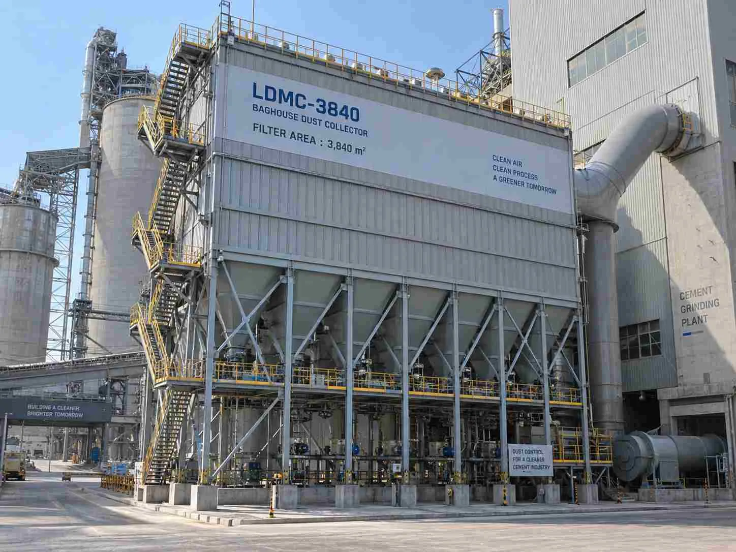
A cement grinding plant needed steadier extraction without reducing production. This representative LDMC Baghouse Dust Collector installation examines an LDMC-3840 configuration, an illustrative outlet reduction from 35 to 8 mg/m³, and the engineering checks required to substantiate that result.
The panel distinguishes the scenario from confirmed product information.
An LDMC Baghouse Dust Collector can support cement mill dust collection when airflow, available filter area, dust discharge and cleaning capacity are specified together. This representative LDMC-3840 example uses a 10 mg/m³ outlet target and illustrates why sizing must allow for an isolated compartment. The example is an engineering scenario; Senotay’s published model data do not establish measured performance at a named cement plant.
These illustrative comparisons use June 2026 as the baseline and July 2026 as the operating period; no underlying records have been supplied.
The representative customer operated a cement grinding line at 120 t/h over 24 h/day. The maintenance manager owned extraction reliability, while the environmental manager needed defensible stack results. Both depended on the same collector, but judged success differently.
The duty combined fine cement particles, abrasive carryover and changing ventilation demand. Production interruptions created restart work and scheduling pressure. The plant needed captured material returned through an approved process route without allowing hopper accumulation to interrupt filtration. A clear stack alone would not demonstrate that the mill retained adequate ventilation.
The plant experienced declining suction during extended production runs. Operators saw dust escape around process interfaces while the collector pressure differential increased. The difficulty became more apparent during sustained loading, when cleaning no longer restored the previous operating condition.
The representative maintenance team shortened the cleaning interval and replaced visibly damaged bags. Those actions addressed immediate symptoms, but extraction weakened again because the underlying restriction and dust-discharge conditions remained unresolved. More frequent pulsing also increased demand on the compressed-air header.
Doing nothing meant accepting recurrent dust-related stops, cleaning labour and uncertainty over outlet performance. However, the plant could not assume that installing a larger fan would fix the problem: additional airflow could increase filtration velocity and aggravate dust re-entrainment.
The awkward constraint was the existing support position and overhead maintenance access. Any replacement needed to fit the available installation arrangement while allowing bags and cages to be removed safely. Production also required a short, planned connection outage.
A baghouse loses airflow when resistance increases beyond the pressure the fan can overcome at the required operating point.
Dust cake is the layer of collected particles on the filter surface. Differential pressure is the pressure difference between the dirty and clean sides of the collector. Blinding is persistent blockage of the filter medium that normal cleaning cannot adequately remove.
Particles accumulate as gas passes through the bags. A controlled deposit helps capture fine particles, but a thicker or less permeable deposit requires more pressure to pass the same gas volume. The EPA’s explanation of fabric-filter operationdescribes the relationship between dust accumulation, pressure drop and periodic cleaning.
A pulse briefly flexes the bag and releases deposited material. Offline cleaning isolates a section so that reduced gas movement gives released dust a better opportunity to fall.
However, filtration is not complete when dust leaves the bag. Dust must pass through the hopper and discharge equipment. Accumulation can expose bags to re-entrained material.
A rising pressure trend can indicate excess filtration velocity, inadequate pulses, moisture-related deposits or obstructed discharge. These causes require different corrections. Check operating conditions and dust removal before increasing pulse pressure; harder cleaning cannot reliably reverse cement deposits that have become bonded to the medium.
The representative project used an outlet acceptance target of 10 mg/m³ on a dry standard basis. That figure is a proposed contractual requirement, not a verified statutory limit for an unidentified plant. The actual permit, location-specific requirements and applicable cement-sector rules must determine the final compliance obligation.
The requirements separate mandatory conditions from preferences.
The alternatives address different causes and should be compared before selecting equipment.
Repair wins when the existing filter area and housing remain adequate. A cyclone can reduce coarse loading, but should not be assumed to satisfy a demanding fine-particle outlet target.
A long-bag collector is the wrong choice where maintenance clearance is unavailable. Wet, condensing gas also requires conditioning and suitable media before a dry filter becomes a defensible selection.
No customer procurement records establish why Senotay won an actual order. In the representative evaluation, acceptance depended on demonstrating available filter area during isolation, a workable dust-discharge arrangement and an agreed emissions test.
A catalogue efficiency percentage would not have resolved those questions. The required evidence was an approved arrangement drawing, duty-specific media selection and a written performance guarantee identifying operating conditions.
Within the representative scenario, we supplied one Senotay LDMC-3840 long-bag collector, with compartment isolation, pulse cleaning and continuous hopper discharge.
The published model listing identifies 3,840 m² of filter area, 1,280 bags and 80 solenoid valves. The following project-specific selections remain provisional:
Operating airflow: 200,000 m³/h at actual inlet conditions.
Compartment arrangement: 8 equal sections.
Housing material: Q235B, subject to structural approval.
Filter medium: polyester needlefelt, subject to gas-condition review.
Cage material: galvanized Q235B.
Instrumentation: differential pressure, inlet temperature and hopper level.
Cleaning control: demand-based sequencing with isolation interlocks.
We chose → 8 isolatable sections over → whole-collector cleaning because → 3,360 m² would remain available with one section offline, giving approximately 0.99 m/min at the representative airflow.
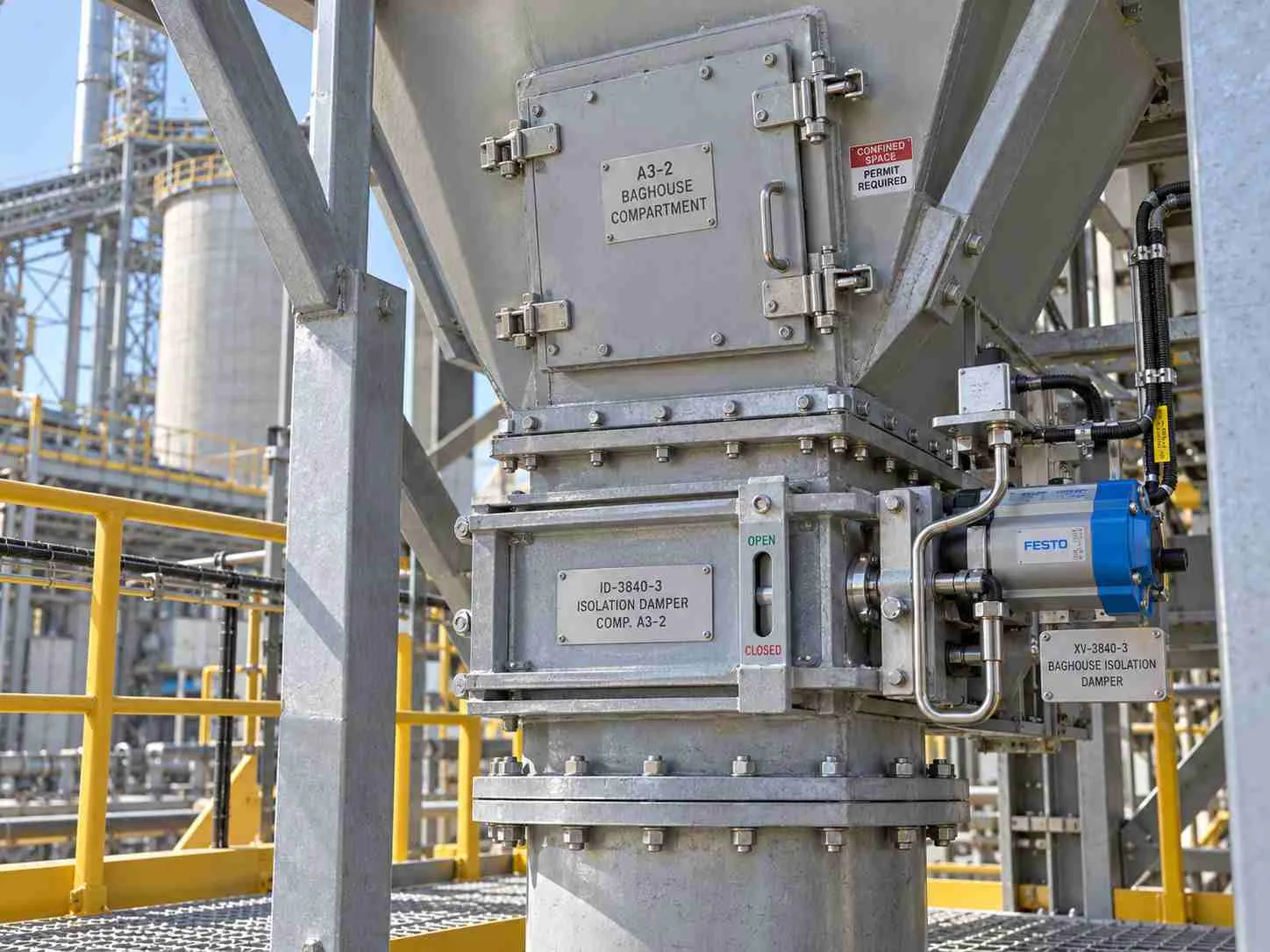
We chose → differential-pressure demand over → a permanently shortened timer because → the proposed 1,200–1,600 Pa operating band provided a condition-based trigger. Final settings would depend on commissioning observations and media limits.
We chose → continuous discharge over → intermittent emptying because → a representative 20 g/m³ actual inlet loading corresponds to 4,000 kg/h entering the collector. Discharge sizing still requires peak loading and bulk-density data.
The model designation came from the published range. Compartment layout, controls, connections and media require order-specific confirmation.
The accepted trade-off was maintenance height: long bags conserve plan area but demand a verified lifting and removal arrangement. Compartment isolation also increases the loading on the sections that remain online.
The following route describes a proposed build record; it does not document an actual Senotay production order. The factory capability pageprovides supplier context, but does not establish the machines, tolerances or inspection results for this scenario.
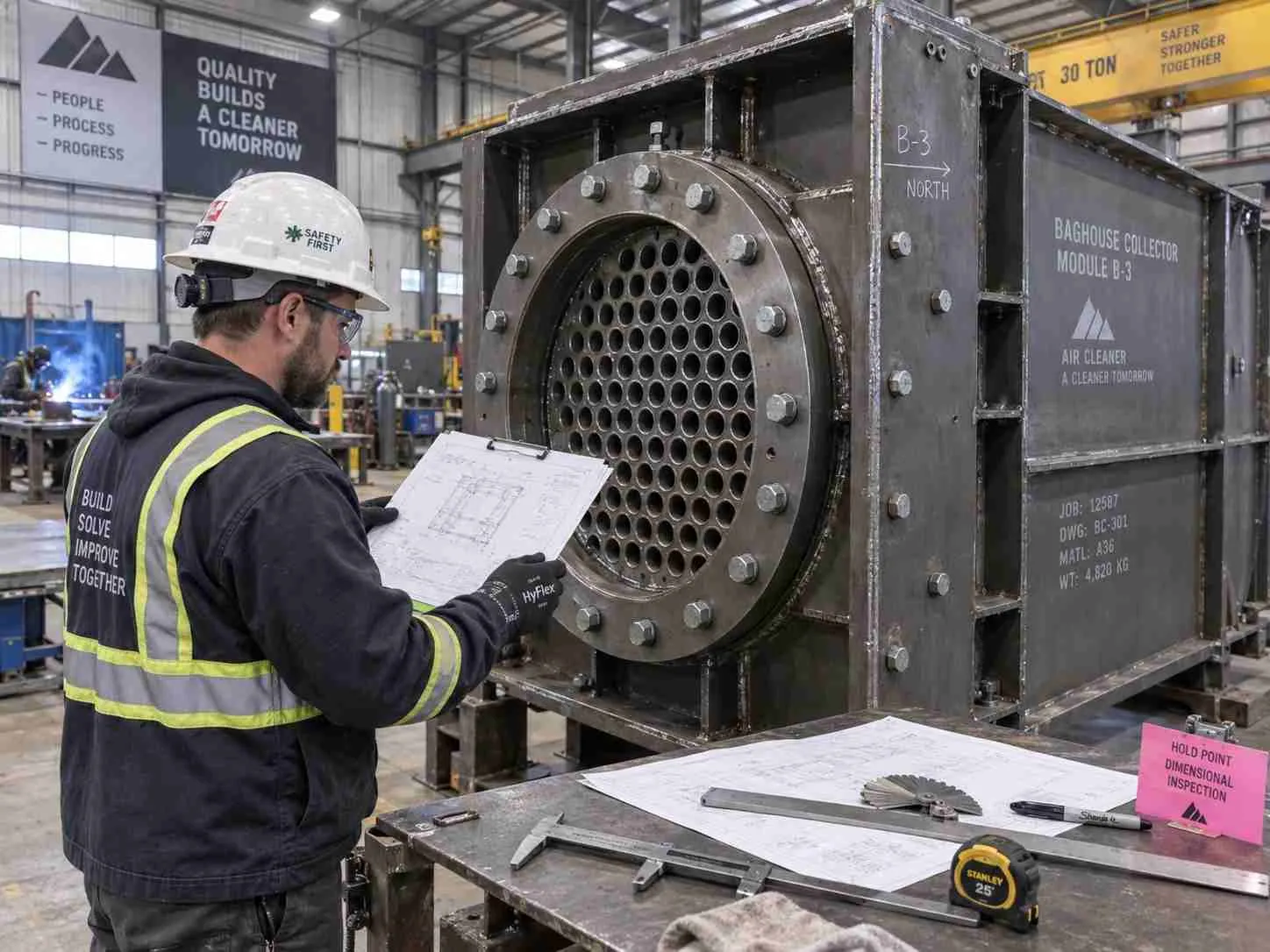
We checked Q235B material identification against the approved bill of materials, then cut shell panels and formed hopper sections. CNC cutting and press-brake capacity would need to match the approved plate thickness and bend lengths; those machine ratings remain unconfirmed.
We machined or cut bag-seat openings to the approved bag-interface drawing, assembled the housing and joined panels using a controlled welding sequence. The representative dimensional target was ±1.0 mm at specified module interface datums, checked using calibrated dimensional instruments before trial assembly.
In the representative build, a mating flange moved outside the agreed fit-up tolerance after welding. We corrected the flange and repeated the trial fit. This illustrative second assembly attempt belongs in the production record before it can become a factual manufacturing claim.
Surface preparation and coating followed the approved corrosion specification. We then assembled cages, bags, valves and instruments, checked identification, tested operation and protected components for transport.
The 8-week allowance comprised 2 weeks for engineering, 3 weeks for fabrication, 1 week for coating, 1 week for assembly and testing, and 1 week for packing and release. Transport and site construction were separate.
HJ 836-2017 establishes a low-concentration particulate measurement method; it does not certify a baghouse or set this project’s emission limit.
The official HJ 836-2017 textspecifies dry standard conditions of 273.15 K and 101,325 Pa. A qualified testing team samples at the stack plane and determines collected particulate mass relative to sampled gas volume.
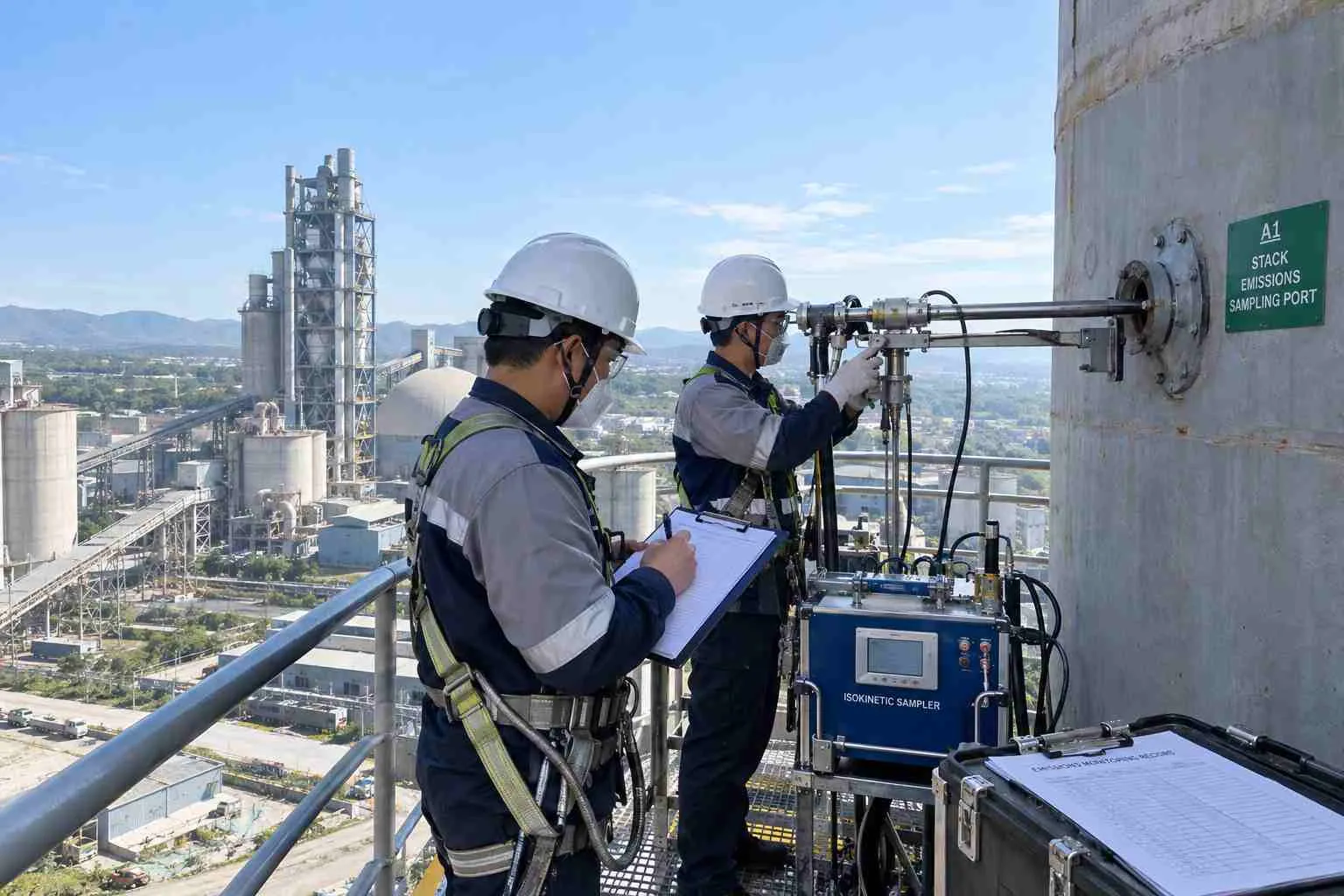
For this scenario, the proposed acceptance programme uses 3 runs of 60 min at stable production. That schedule is a project proposal, not a quoted requirement of HJ 836-2017. A failed result triggers investigation, correction and repeat acceptance testing; legal consequences depend on the permit.
The table identifies planned checks, not completed certificates.
The quality-control pageshould be supplemented with current, scope-specific documents before certification claims are published.
The representative installation included an interference between the planned discharge connection and an existing support. We revised the connection arrangement before loading the hopper. That event remains illustrative and requires a site record.
Commissioning began with instrument checks, discharge rotation and isolation interlocks. The fan duty was then established with production operating, followed by cleaning adjustment and outlet testing.
Handover included the approved drawings, operating manual, alarm responses, bag-replacement procedure and recommended valve spares. Training focused on recognizing a restricted hopper, interpreting pressure trends and distinguishing a leakage alarm from a process-flow disturbance.
The comparison below uses representative June 2026 baseline data and July 2026 operating data. Both periods assume comparable production duty; all measurements remain unverified.
The illustrative outlet change is a 77% reduction, calculated as (35 − 8) ÷ 35 × 100. It is neither a measured result nor a collection-efficiency calculation.
The commercial benefit would come primarily from recovered operating time. Multiplying 9 h/month by 120 t/h gives a theoretical 1,080 t/month of available production opportunity. Actual additional sales depend on demand, scheduling and downstream capacity.
An unpromised benefit in the scenario was easier fault diagnosis from clearer alarm records. Operating throughput did not increase. No electricity saving or payback period is claimed because comparable energy readings, investment cost and operating expenses are unavailable.
Specify airflow and usable filter area together before comparing prices.
Air-to-cloth ratio is gas volume per minute divided by the filter area available to pass that gas.The EPA baghouse design chapteridentifies gas-to-cloth ratio as a principal sizing parameter.
Filtration velocity (m/min) = Actual airflow (m³/h) ÷ [60 × Online filter area (m²)]
“Online filter area” means the filter area available to pass gas while a compartment is isolated for cleaning. The factor of 60 converts airflow from cubic metres per hour to cubic metres per minute.
For the representative LDMC-3840 configuration:
Total installed filter area: 3,840 m²
Assumed arrangement: 8 equal compartments
Compartments remaining online during cleaning: 7
Online filter area = 3,840 × (7 ÷ 8) = 3,360 m²
At an actual airflow of 200,000 m³/h:
Filtration velocity during cleaning = 200,000 ÷ (60 × 3,360) = 0.992 m/min
Using all installed filter area instead:
Filtration velocity with all compartments online = 200,000 ÷ (60 × 3,840) = 0.868 m/min
Sizing only against the total installed area understates the filtration velocity during compartment cleaning. Both calculations use representative operating assumptions, not measured project performance.
Incoming dust load (kg/h) = Actual airflow (m³/h) × Inlet dust concentration (g/m³) ÷ 1,000
The factor of 1,000 converts grams to kilograms. Airflow and dust concentration must use the same gas-volume reference conditions.
For the representative operating conditions:
Incoming dust load = 200,000 × 20 ÷ 1,000 = 4,000 kg/h
The collector therefore receives a calculated 4,000 kg/h of dust under these assumptions. This is incoming dust mass, not a measured recovery rate or a quantity of saleable product. Hopper and discharge sizing must also account for peak loading, bulk density and material flow behaviour.
Filtration velocity (m/min) = Actual airflow (m³/h) ÷ [60 × Online filter area (m²)]
“Online filter area” means the filter area available to pass gas while a compartment is isolated for cleaning. The factor of 60 converts airflow from cubic metres per hour to cubic metres per minute.
For the representative LDMC-3840 configuration:
Total installed filter area: 3,840 m²
Assumed arrangement: 8 equal compartments
Compartments remaining online during cleaning: 7
Online filter area = 3,840 × (7 ÷ 8) = 3,360 m²
At an actual airflow of 200,000 m³/h:
Filtration velocity during cleaning = 200,000 ÷ (60 × 3,360) = 0.992 m/min
Using all installed filter area instead:
Filtration velocity with all compartments online = 200,000 ÷ (60 × 3,840) = 0.868 m/min
Sizing only against the total installed area understates the filtration velocity during compartment cleaning. Both calculations use representative operating assumptions, not measured project performance.
Incoming dust load (kg/h) = Actual airflow (m³/h) × Inlet dust concentration (g/m³) ÷ 1,000
The factor of 1,000 converts grams to kilograms. Airflow and dust concentration must use the same gas-volume reference conditions.
For the representative operating conditions:
Incoming dust load = 200,000 × 20 ÷ 1,000 = 4,000 kg/h
The collector therefore receives a calculated 4,000 kg/h of dust under these assumptions. This is incoming dust mass, not a measured recovery rate or a quantity of saleable product. Hopper and discharge sizing must also account for peak loading, bulk density and material flow behaviour.
Actual airflow across minimum, normal and peak operation.
Dust loading, particle distribution and bulk density.
Temperature, moisture and relevant gas chemistry.
Outlet requirement with its measurement basis and averaging period.
Ask any supplier how much area remains online, which operating conditions the guarantee covers, what happens when discharge stops, and how replacement bags will be removed.
Request fan selection against total system resistance. Collector pressure drop alone excludes duct, hood and other system losses.
Maintenance should interpret pressure, airflow and outlet dust together. One reading rarely distinguishes every failure.
The following checks connect symptoms with plausible causes.
Establish a clean, commissioned baseline at a recorded production condition. Compare later trends at similar airflow so changing process demand does not masquerade as filter deterioration.
Do not adopt a calendar bag-life promise without operating evidence. Moisture excursions, abrasive attack and cleaning conditions can change replacement needs substantially. Record the failure location and appearance whenever a bag is removed.
Senotay’s published model table lists the following configurations. Airflow has been converted from the source’s 10410^4 m³/h notation.
The representative supplied selection is LDMC-3840. Motor power, final dimensions, bag geometry, compartment arrangement and media grade require an approved order datasheet. In the published LDMC model table, this configuration is one of 10 in the range.
Ans:No; collection efficiency alone does not prove compliance with an outlet concentration limit. Efficiency compares inlet and outlet particulate mass rates, while a permit may regulate concentration under specified reference conditions. Request the outlet test, operating load, sampling method and applicable acceptance limit together.
Ans:Yes, if the remaining compartments can handle the required airflow. The representative arrangement leaves 3,360 m² online during isolation, but the actual compartment layout requires confirmation. Ask for the online-area calculation and the control sequence rather than assuming all installed area remains available.
Ans:A cyclone can replace the baghouse only where its demonstrated particle capture meets the actual requirement. Cyclones are useful for coarse separation, but fine cement dust may require fabric filtration. Compare outlet performance at the real particle distribution, not equipment purchase price alone.
Ans:No; the 10 mg/m³ figure is a representative contractual target, not an established guarantee for this installation. Senotay’s public page contains inconsistent emissions figures. The purchase agreement must state the guaranteed outlet concentration, gas conditions, loading range and acceptance method before performance can be represented as contractual.
Ans:Price and delivery depend on the approved airflow, media, materials, structural scope, controls and shipping arrangement. The representative supply programme allows 8 weeks, but it is not a supplier commitment. Request an itemized quotation separating equipment, transport, site work, commissioning and recommended replacement parts.
For a preliminary review, send airflow, temperature, dust loading and the outlet requirement. For a firm offer, add the layout and permit conditions through Senotay’s quotation contact. Request a written scope, exclusions and response date; turnaround remains to be agreed.
Related reading
Single pulse bag filter application: Related filtration material; not evidence for this LDMC scenario.
Senotay project index: Browse available project information.
Same-industry verified installation: editorial link pending.
Same-product installation in another industry: editorial link pending.