
EN
What are you looking for?

A metal-coating plant needed stable VOC control through changing paint batches. This representative Type 9 Catalytic Combustion Dust Collector case examines a 20,000 m³/h exhaust duty, an illustrative 500-to-20 ppmv result, and the controls needed to protect catalyst activity.
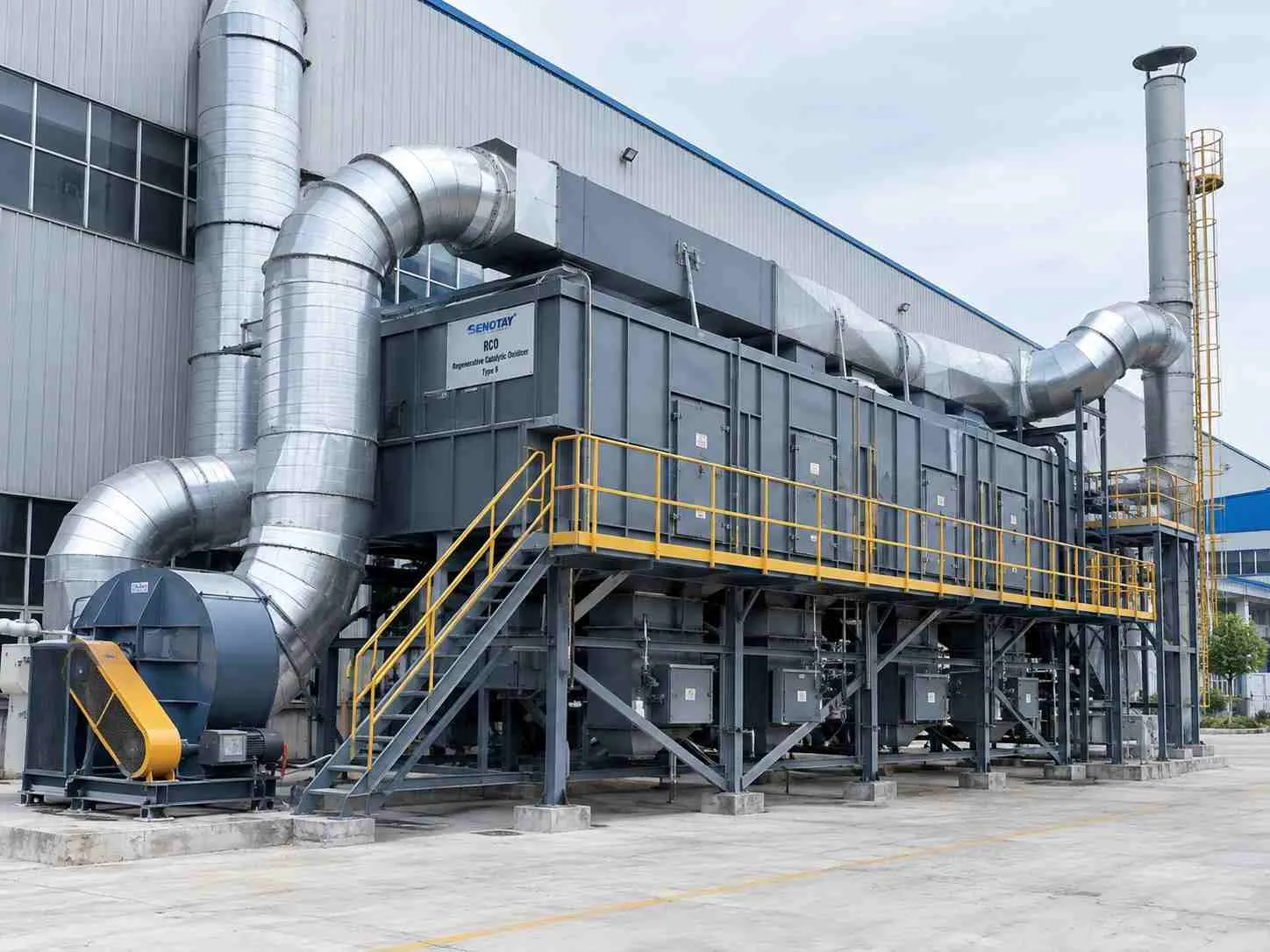 Can catalytic oxidation control VOCs from an industrial coating line?
Catalytic oxidation can control compatible coating VOCs when the exhaust composition, concentration, temperature and oxygen content stay within the approved envelope. Pre-filtration protects the catalyst from particulate fouling, while the catalyst promotes oxidation at lower temperatures than direct thermal treatment.
In this illustrative case, total gaseous organics fall from 500 to 20 ppmv as propane at 20,000 m³/h. Only testing can verify that result.
The scenario compares 1–7 June 2026 with 1–7 July 2026. All figures are representative inputs awaiting project evidence.
The representative plant coated fabricated metal parts on one batch line. Primer and finish recipes changed with customer orders, so exhaust composition and solvent loading varied during spraying, flash-off and curing.
The assumed treatment duty was 20,000 actual m³/h at 45 °C. The project therefore needed a defined VOC inventory, peak-loading basis and operating interlocks before equipment selection.
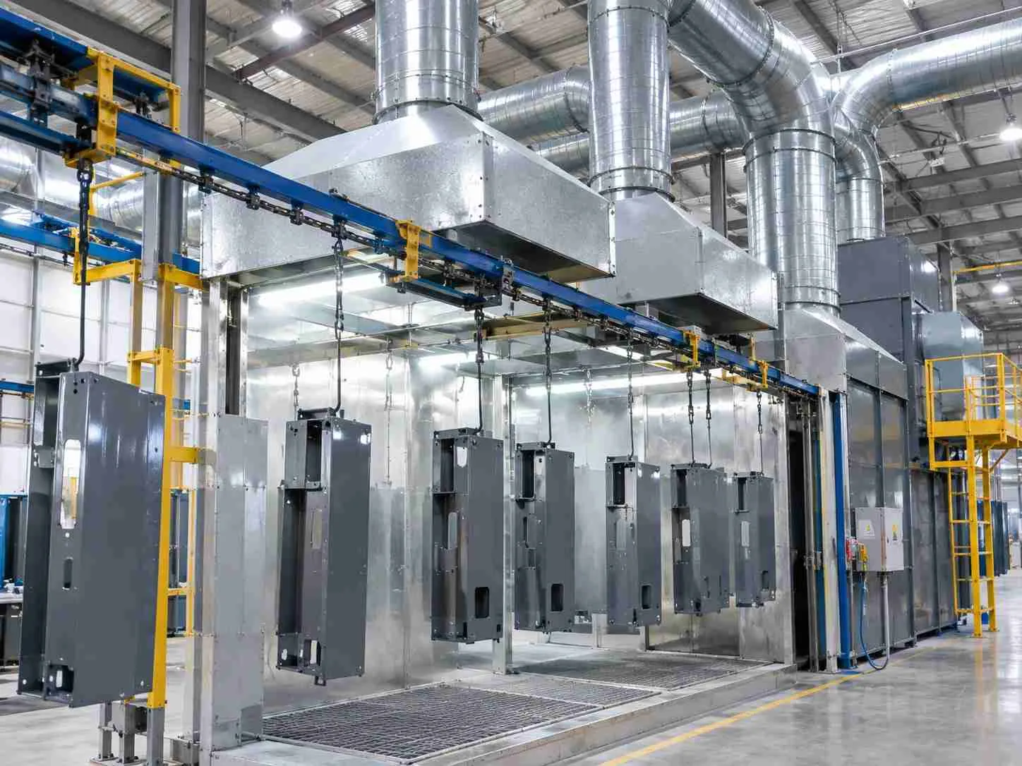
The existing exhaust system maintained booth ventilation but discharged untreated mixed-solvent vapours. Batch changes caused the largest concentration swings.
The team first considered increasing general ventilation to dilute the peaks. More dilution lowered concentration but increased the gas volume requiring treatment and heating. It also did not reduce the VOC mass released from the process. Dilution therefore moved the design problem rather than solving it.
The difficult constraint was the changing solvent mix. Halogenated compounds, sulfur, silicon-containing materials, phosphorus, metals and particulates can poison, mask or foul some catalysts.
No oxidizer selection could be credible until the plant identified normal recipes, cleaning solvents, upset materials and the highest short-duration mass loading.
Oxidation converts suitable organic compounds mainly into carbon dioxide and water when temperature, oxygen, mixing and reaction time are adequate. A catalyst provides an active surface that increases the reaction rate, allowing oxidation at a lower temperature than a comparable thermal oxidizer.
EPA identifies catalyst-bed inlet temperature, outlet VOC concentration and catalyst activity as primary performance indicators for catalytic oxidizers. Temperature rise, outlet temperature, carbon monoxide, oxygen, flow and pressure differential provide additional diagnostic information. See EPA’s catalytic oxidizer monitoring guidance. US EPA
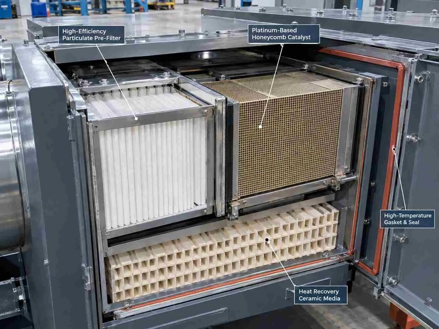
A catalytic oxidizer treats gaseous organic compounds; it is not a primary collector for a heavy dust stream. The pre-filter protects the heat exchanger and catalyst from paint solids and other particulates.
Loading the catalyst with dust can block gas paths, increase pressure loss and conceal the active surface. A pre-filter cannot remove every catalyst poison in vapour form, and an ordinary particulate filter does not control gaseous VOCs.
A heat exchanger transfers heat from treated gas to incoming exhaust. It can reduce auxiliary heating after the system reaches stable operation.
The temperature rise across the catalyst may indicate oxidation, but temperature alone does not quantify destruction. Acceptance requires pollutant measurements at defined production conditions and a stated reporting basis.
The representative contract separates the outlet target from operating safeguards. The 30 ppmv value is an assumed contractual limit, not a universal regulatory requirement.
Source reduction should be assessed first because avoided solvent does not require downstream destruction. Carbon adsorption can suit lower, compatible loads where breakthrough monitoring and media handling are practical.
A thermal oxidizer may be preferable when the exhaust contains catalyst poisons that pretreatment cannot manage. Catalytic treatment is the wrong answer when the stream is poorly characterized, contains incompatible contaminants, lacks adequate oxygen or cannot remain inside the approved safety envelope.
No purchase record establishes why a real customer chose Senotay. For this representative selection, the buyer would require a complete solvent inventory, peak concentration profile, catalyst-compatibility statement, pressure-loss curve and acceptance protocol.
For the representative design, we selected Type 9 from Senotay’s catalytic combustion range. The configuration below is proposed, not evidence of a shipment. Senotay publishes Type 9 with 20,000 m³/h airflow, a 380–450 °C temperature range, platinum-based catalyst, 99% claimed VOC removal and 45 kW power. Factory Price
The package comprised:
A controlled pre-filter for paint particulate, with differential-pressure indication.
A regenerative heat-recovery section and catalyst chamber.
A platinum-based catalyst, subject to written compatibility confirmation.
Temperature, pressure, airflow, oxygen and VOC monitoring interfaces.
Bypass, purge and shutdown logic defined by a project hazard assessment.
We chose Type 9 → over Type 8 → because the assumed 20,000 m³/h duty matches Type 9’s published airflow, while Type 8 is listed at 15,000 m³/h. Final selection still requires the manufacturer’s fan and pressure calculation.
We chose a 380 °C representative catalyst-inlet setpoint → over using the lowest catalogue temperature → because the stated coating duty required a defined operating margin for the approved VOC mixture. Catalyst supplier data and commissioning tests must establish the actual setpoint.
We chose paired inlet/outlet mass-flow acceptance → over outlet concentration alone → because increased dilution could lower ppmv without destroying VOC mass. Flow, moisture and calibration basis must remain consistent across the calculation.
The Type 9 designation anchors the enquiry. Catalyst volume, heat-storage media, residence time, filtration grade, materials, burner or heater details and control logic require a signed project schedule.
The accepted trade-off was additional pressure loss, electrical demand and catalyst-management work. The project sought lower VOC emissions, not zero carbon dioxide production. Complete oxidation converts carbon in the captured VOC to carbon dioxide, so the process does not constitute carbon removal.
The route below is proposed; no production traveller was supplied. Senotay’s factory information provides company context but does not verify this project’s manufacturing records.
Fabrication would begin with traceable casing and high-temperature internal materials. CNC cutting and forming would prepare panels, flanges, plenums and access openings.
The fabricator would join the casing, fit internal supports and inspect welds and seals before installing insulation.
The representative catalyst-frame positional tolerance is ±2 mm against the approved drawing, verified with calibrated dimensional tools. Heat-recovery media, catalyst modules, filters, sensors and access doors would then be assembled in sequence. A cold leak test and control simulation would precede hot commissioning.
The illustrative 12-week programme allocates:
3 weeks to engineering and procurement.
5 weeks to casing and internal fabrication.
2 weeks to assembly and factory checks.
2 weeks of packing and shipment preparation.
Maintaining sealed, even flow through the catalyst modules is the anticipated difficult step.
EPA Method 25A measures total gaseous organic concentration using a flame-ionization analyzer. Results are expressed as propane, another appropriate calibration gas, or carbon equivalents.
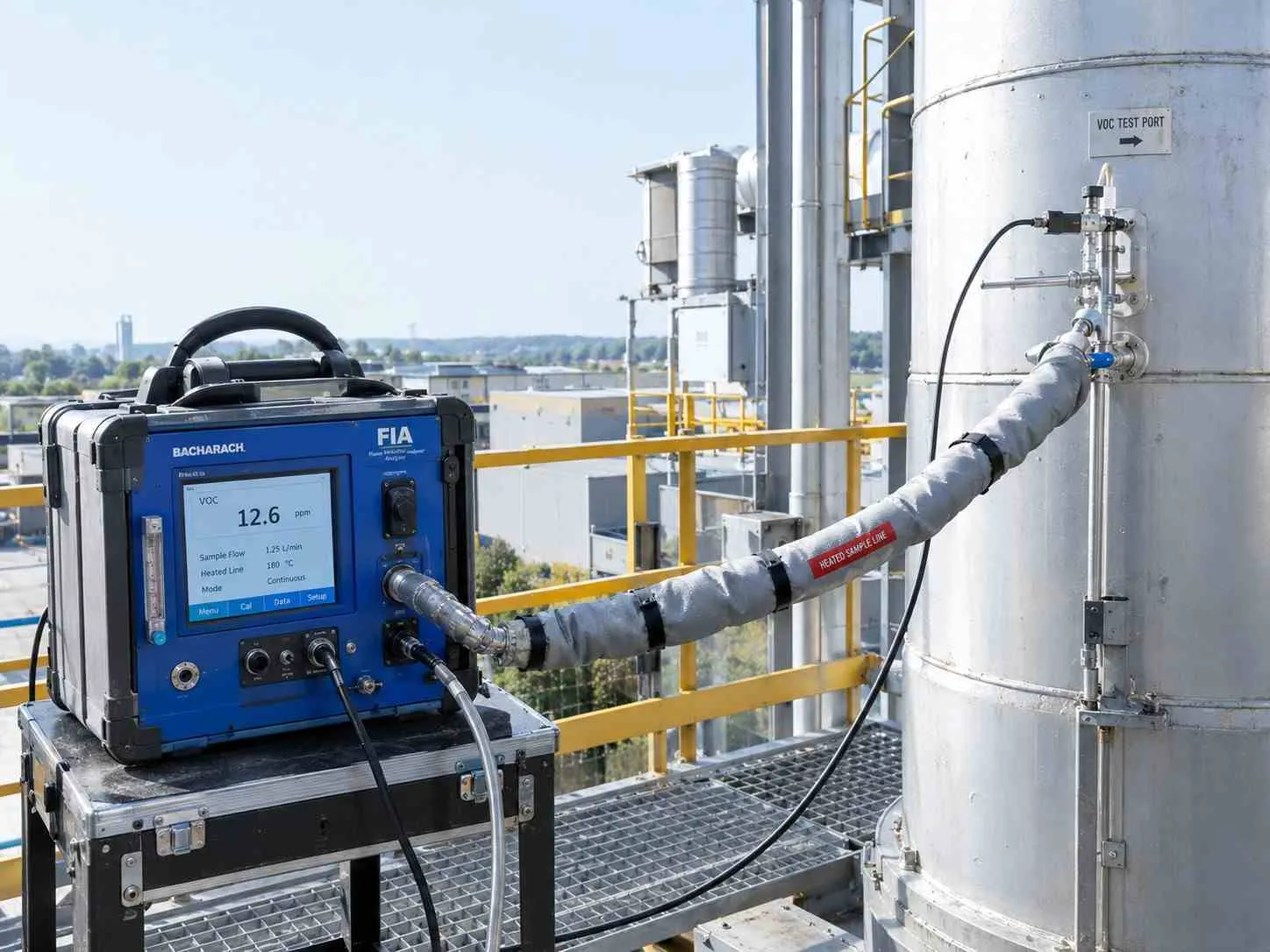
The method is principally applicable to vapours consisting of alkanes, alkenes and aromatic hydrocarbons. The tester must evaluate its suitability for the actual mixture. It also requires a heated sample path and calibration checks. epa.gov
Method 25A is a measurement method, not a universal VOC limit. For this representative contract, an independent organization would test inlet and outlet during 3 runs of 60 minutes at an agreed high-load recipe. The duration is a project assumption rather than a universal Method 25A requirement.
A failed test triggers investigation, correction and retesting. Statutory consequences depend on the actual permit.
The table shows required evidence rather than completed checks. Senotay’s quality-control informationdoes not replace project records.
The illustrative startup problem occurred when a maintenance cleaning solvent absent from the original inventory entered the exhaust. The VOC concentration increased rapidly, and the high-concentration interlock paused process exhaust admission while the system completed its approved safe sequence.
The team added the solvent to the inventory and revised the cleaning procedure before retesting. This is a representative event, not a documented incident.
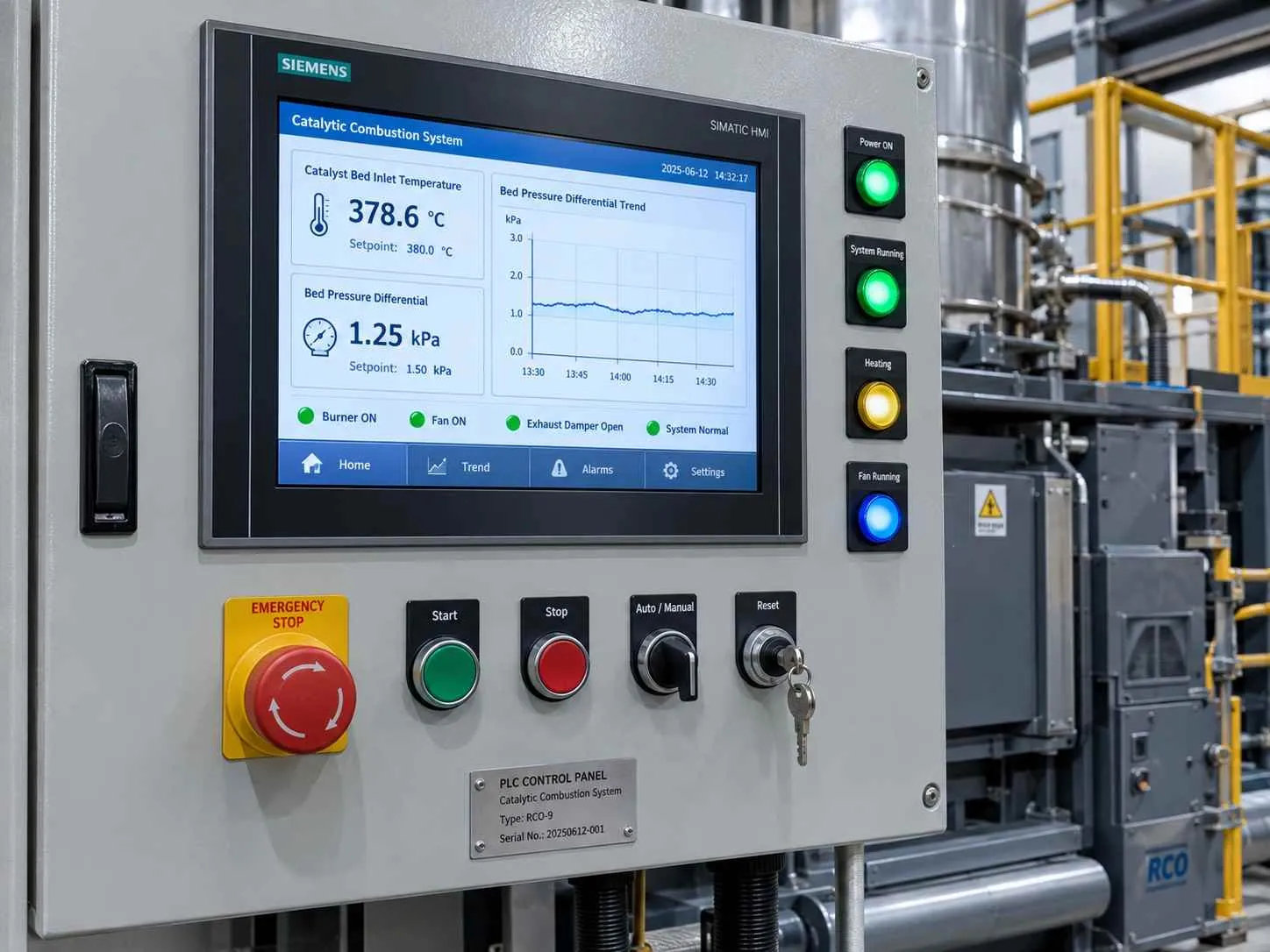
Commissioning would establish purge flow, pressure loss, temperature profile, heat-recovery cycling and catalyst response using approved production recipes. The team would verify that booth capture remained acceptable after adding the oxidizer resistance.
Handover would include the solvent inventory, operating envelope, alarm response, filter servicing, catalyst inspection, startup and shutdown procedures, drawings and critical spares.
The comparison covers 1–7 June 2026 and 1–7 July 2026. These are illustrative values and dates, not field measurements.
The illustrative concentration reduction is:
(500 ppmv − 20 ppmv) ÷ 500 ppmv × 100 = 96%.
If inlet and outlet gas mass flows differ, destruction efficiency must use mass flow rather than this concentration shortcut.
The unpromised benefit in the scenario is better recipe control: the VOC trend helps production identify a coating or cleaning change that falls outside the approved inventory.
Electrical demand does not improve. Heat recovery may reduce auxiliary heating after warm-up, but no energy saving is claimed without a verified baseline covering startup, production and standby. A payback calculation also needs installed cost, energy, catalyst, filter, maintenance and usable production-value records.
"Until we complete paired inlet and outlet mass-flow testing across our varying paint batches, our primary focus remains on tracking solvent inventories and protecting catalyst activity from unexpected cleaning agents."
— Mr.Li , Production Operations Manager, Li-Wu metalwork.
The basic calculation compares inlet and outlet VOC mass flow on compatible bases.
Destruction efficiency (%) = (inlet VOC mass flow − outlet VOC mass flow) ÷ inlet VOC mass flow × 100
VOC mass flow = gas flow × VOC concentration
Both terms must first be converted to compatible temperature, pressure, moisture and calibration bases.
If gas flow is unchanged and both readings use the same dry basis and propane calibration:
Destruction efficiency = (500 − 20) ÷ 500 × 100 = 96%.
At an illustrative inlet mass flow of 25 kg/h:
Outlet mass flow = 25 kg/h × (1 − 0.96) = 1.0 kg/h.
VOC mass destroyed = 25 kg/h − 1.0 kg/h = 24 kg/h.
The 25 kg/h value is representative.
The supplier must assess peak mass loading, heating value, oxygen, lower flammable limit, residence time and allowable temperature rise. Establish the fastest credible release from spray, flash-off, cleaning and upset activities.
Before requesting a quote, provide:
Actual and maximum exhaust flow.
Complete VOC species inventory.
Normal and peak inlet concentration.
Particulate and aerosol loading.
Oxygen and humidity.
Minimum and maximum exhaust temperature.
Production and cleaning schedules.
Ask every supplier for catalyst compatibility, expected pressure loss, operating-temperature window, safety interlocks, test basis and performance exclusions.
Trend catalyst temperature, pressure differential, VOC outlet and production recipe together. One normal parameter cannot prove correct operation.
Do not clean or regenerate catalyst without the supplier’s approved procedure. Some contaminants chemically poison active sites and cannot be removed by heating.
Record pressure and temperature at consistent production conditions so maintenance can distinguish normal recipe changes from equipment deterioration.
Senotay publishes the following type table. Values are catalogue claims rather than project guarantees. Factory Price
The representative selection is Type 9. Catalyst volume, filtration, dimensions, heat recovery and control scope require a signed schedule. This configuration is one of 10 in the published range.
Ans: Only if the supplied package includes suitable particulate control. Catalytic oxidation treats compatible gas-phase organics, while the pre-filter protects the catalyst. Heavy dust, sticky aerosol or overspray may require dedicated upstream separation. Ask the supplier to state each stage’s duty and guarantee separately.
Ans: No. Compliance depends on the applicable pollutant definition, outlet limit, flow, averaging period, operating conditions and test method. Ninety-nine percent removal from a high inlet loading can still leave an excessive outlet concentration. Require both a destruction target and an outlet limit where the permit demands them.
Ans: No. Catalyst suitability depends on the complete solvent and contaminant inventory. Halogens, sulfur, silicon compounds, phosphorus, metals and particulate may reduce activity or damage equipment. Include cleaning chemicals and rare recipes in the review, not only the most common coating.
Ans: Activated carbon may suit lower, compatible VOC loadings where adsorption capacity, breakthrough monitoring and media handling are practical. It transfers VOC to the media rather than destroying it unless the media is regenerated. Compare fire risk, disposal, regeneration, energy and peak loading for the actual stream.
Ans: There is no defensible universal interval. Life depends on catalyst type, contaminants, temperature, loading and maintenance. Senotay publishes both 12,000–20,000 hours and 3–5 years in different sections; the supplier must reconcile those values and define the activity test and replacement criterion.
Ans: Provide gas flow and conditions, VOC species and concentration profile, particulate and aerosol data, oxygen, production schedule and applicable outlet requirements. Include site layout, utilities and safety information. Ask for the complete scope, exclusions, operating-cost assumptions, commissioning plan and emissions-test responsibilities.
For an initial review, send the solvent inventory, flow data and existing emissions results. For a quotation, add the layout, utilities and acceptance conditions through Senotay’s enquiry page. Request an initial scope response within 2 working days; supplier agreement is required.
Related reading:
Cartridge dust collectors: assess particulate pretreatment before the catalyst.
PP spray towers: compare absorption for soluble gases with VOC oxidation.
Senotay application cases: request a verified coating-line installation and another Type 9 reference before relying on comparable performance.