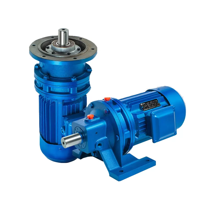
High-Torque Overhead Drive: The SENOTAY Cycloid Vertical Reducer
Maximize your vertical drive performance with the SENOTAY Vertical Cycloid Series—the ultimate solution for space-saving, flange-mounted speed reduction from Hebei OuTai Environmental Protection Equipment Co., Ltd. (SENOTAY). Engineered specifically for top-down or bottom-up driving configurations, our vertical cycloidal pin-wheel reducers deliver massive torque output, exceptional shock resistance, and near-zero sliding friction within a compact vertical footprint. This makes them the premier choice for industrial mixers, wastewater agitators, vertical bucket elevators, and automated chemical processing lines.
Why Leading Factories Choose SENOTAY:
Factory-Direct Pricing. Certified Quality. Dedicated Support.
Best Price Guarantee
No markups. No hidden fees. Just professional-grade vertical speed reducers at wholesale prices – direct from our manufacturing floor to your facility.
Certified & Compliant
ISO 9001 and CE certified. Our vertical reducers are built to rigorous global engineering standards, utilizing precision-hardened internal components to minimize friction and ensure long-term operational safety under continuous-duty, high-overload conditions.
Fast, Free Shipping
We ship fast because downtime is expensive. Most standard vertical cycloid models leave our regional warehouses within 48-72 hours, with reliable global shipping available to most areas.
Comprehensive After-Sales Support
Lifetime Technical Support: Expert guidance for torque sizing, radial/axial load calculations, and vertical shaft alignment.
Spare Parts in Stock: Immediate availability of specialized vertical oil seals, eccentric bearings, cycloidal plates, and pin teeth.
Remote Troubleshooting: Fast diagnostics to keep your mixing, lifting, and driving lines moving.
Trusted by factories worldwide. Ready for yours.
Product Description & Material Properties
Senotay’s Cycloid Vertical Reducer (Model: CVR-XX-YY-ZZ) is manufactured with premium-grade materials designed for long-life performance in continuous-duty industrial environments.
Parameter | Specification | Details / Material Grade |
Model | CVR-XX-YY-ZZ | Customizable for ratio, frame, and mounting |
Reduction Ratios | 1:11 to 1:119 | Single-stage configuration |
Input Power | 0.18 – 37.0 kW | Continuous Duty S1 |
Output Torque | 150 – 42,000 Nm | Peak torque 220% of rated |
Efficiency | 82% – 91% | Ratio dependent |
Housing Material | Cast Iron (GG30/EN-GJL-300) or Aluminum Alloy | EN 10204 3.1 certified |
Gear Material | 18CrNiMo7-6, 42CrMo4, GCr15SiMn | Case-carburized, HRC 60±2 |
Lubrication | Lithium Complex Grease / Synthetic PAO Oil | DIN 51825 KP2N-30 / ISO VG 220 |
IP Rating | IP66 (Standard) / IP68 (Optional) | Sealed double/triple lip design |
Noise Level | 58 – 72 dB(A) | Measured at 1m distance @75% load |
These premium materials ensure superior hardness, shock resistance, thermal stability, and corrosion protection for 24/7 industrial operations.
Cycloid Vertical Reducer Types and Specifications
Model Type | Reduction Ratio (i) | Output Torque (Nm) | Efficiency (%) | Input Power (kW) | Mounting Option | Weight (kg) |
CVR-11-037 | 1:11 | 150 | 91 | 0.18 | FV1 | 12 |
CVR-17-050 | 1:17 | 550 | 89 | 0.55 | FV2 | 28 |
CVR-29-075 | 1:29 | 1200 | 88 | 1.5 | FV1 | 45 |
CVR-35-090 | 1:35 | 2300 | 87 | 2.2 | FV3 | 68 |
CVR-43-110 | 1:43 | 3600 | 86 | 4.0 | FV1 | 95 |
CVR-59-132 | 1:59 | 7200 | 85 | 7.5 | FV2 | 160 |
CVR-71-160 | 1:71 | 10500 | 84 | 11 | FV1 | 215 |
CVR-87-180 | 1:87 | 16000 | 83 | 15 | FV3 | 340 |
CVR-119-200 | 1:119 | 32000 | 82 | 30 | FV2 | 480 |
CVR-119-220 | 1:119 | 42000 | 82 | 37 | FV1 | 580 |
Cycloid Vertical Reducer — Technical Specification Table
Physical Dimensions | Performance Ratings | Material & Construction | Operational Data | Certifications & Lifecycle |
Center Height: 90–500 mm | Reduction Ratio: 6:1 – 87:1 | HT250 / QT450 Cast Iron | Rated Input Speed: 1,500 rpm | Design Service Life: ≥ 20,000 h |
Overall Height: 260–1,280 mm | Rated Output Torque: 200–20,000 Nm | 40Cr, HRC 58–62 | Max Input Speed: 1,800 rpm | ISO 9001:2015 |
Overall Diameter: 180–820 mm | Peak Torque Capacity: 2.0 × Rated | GCr15 Bearing Steel | Efficiency: 90–93% | GB/T 19001 |
Output Shaft Dia.: Φ30–Φ130 mm | Backlash: ≤ 1 arc-min | 42CrMo, Heat Treated | Overload Capacity: 200–300% | CE (Optional) |
Input Flange Dia.: Φ100–Φ350 mm | Transmission Accuracy: ≤ 1 arc-min | SKF / NSK / HRB | Noise Level: ≤ 65 dB(A) | RoHS (Optional) |
(BCD): Φ120–Φ400 mm | Torque Density: 32–55 Nm/kg | NBR / Viton | Lubrication Type: Oil Bath | Maintenance Interval: 5,000 h |
Mounting Base Size: 160×160–600×600 mm | Speed Stability: ±0.5% | Grade 10.9 Bolts | Oil Capacity: 1.0–8.0 L | Max Start-Stop Cycles: ≥ 1,000,000 |
Vertical Installation Height: ≤ 40 m | Temperature Rise: ≤ 35°C | Epoxy Anti-corrosion Coating | Operating Temp.: –20 to +80°C | MTBF: ≥ 30,000 h |
Unit Weight: 22–720 kg | Input Power Range: 0.37–75 kW | ISO 1328 Grade 6 | Installation Orientation: Vertical | 12–18 months |

Why Choose Senotay Cycloid Vertical Reducer?
When you choose a Cycloid Vertical Reducer from Senotay, you’re investing in precision engineering, reliability, and long-term cost efficiency.
Key reasons to choose our vertical cycloidal gearbox:
1. High Capacity – Multi-tooth interlocking tooth geometry ensures that both the Kuplex chain and components are utilized to their full capacity, which lowers chain wear and extends service life.
2. High Torque Transmission – The rated torque is available up to 42,000 Nm which makes it ideal for heavy-duty vertical installation.
3. Small, Space-Saving Design – Perfect for Tight Facilities in an Industrial or Commercial Workshop where Space is a Premium without sacrificing power.
4. Low Backlash (≤5 arcmin) -Accuracy & repeatability for automation and CNC applications.
5. Durable Design - High‐strength alloy steel, sealed to IP66 housing and corrosion resistant coatings provide reliable performance in the toughest environments.
6. Energy Saving -Maximizes the electric motor efficiency onto the load and minimizes energy lost.
Cycloid Vertical Reducer Working Mechanism
The Cycloid Vertical Reducer uses a cycloidal motion principle to achieve speed reduction through smooth, balanced torque transmission:
Input Shaft Rotation – The motor drives an eccentric bearing, which initiates controlled cycloidal motion.
Cycloidal Disc Engagement – The hardened cycloidal discs oscillate and mesh with stationary pins in the housing.
Power Output Generation – The oscillating motion is transferred to the output shaft through high-strength needle rollers, generating low-speed, high-torque rotational output.
This innovative design ensures minimal vibration, uniform torque distribution, and ultra-low backlash, making it ideal for high-precision vertical applications.
Key Features of Senotay Cycloid Vertical Reducer
Compact, vertically mounted design for space-saving installation.
High torque density with minimal backlash.
Exceptional shock load absorption.
Precision alignment and smooth operation.
High-grade lubrication for extended maintenance intervals.
IP66-rated for dust and moisture protection.
Multiple mounting options (Flange Input, Hollow Shaft Down, Torque Arm Supported).
Long design life: 25,000 hours (rated) | 60,000+ hours (typical).
Core Components
Cycloidal Discs (18CrNiMo7-6) – High-strength, case-hardened components for torque transfer.
Eccentric Bearing Assembly – Ensures stable rotation.
Pin Ring & Needle Rollers (42CrMo4, GCr15SiMn) – Provides smooth load sharing
Sealed Housing (GG30 Cast Iron) – IP66 protection against dust and liquids..
Output Shaft (ISO 773 Keyway) – High precision and wear-resistant.
Installation Method
Standard Mount (FV1 – Flange Input/Solid Output Down).
Hollow Output Shaft (FV2).
Torque Arm Supported Mount (FV3).
All flanges follow DIN/ISO/SAE standards for universal compatibility.
Technical Advantages in Senotay Manufacturing
Senotay’s advanced CNC machining, heat treatment, and precision metrology systems ensure every Cycloid Vertical Reducer exceeds global performance standards.
Manufacturing strengths include:
CNC precision of ±0.003 mm TIR.
Surface hardening HRC 60±2 for increased wear resistance.
Automated thermal and vibration testing per ISO 10816-3.
Custom configurations (shaft types, flanges, and surface coatings).
Strict quality assurance under ISO 9001:2015 certification.
Senotay focuses on eco-efficient production supported by sustainable lubricants, strict material traceability, and zero-defect quality control.
▪ Industrial Blower Series
▪ Y5-47 Industrial Blower | 4-72 Industrial Blower | 4-68 Industrial Blower | 9-19 Industrial Blower | 9-26 Industrial Blower
▪ Cycloid Reducer Series
▪ Horizontal Cycloid Reducer | Cycloid Vertical Reducer | Bipolar Cycloid Reducer XWE
▪ XLED Type Cycloid Reducer | XW Type Cycloid Reducer | Planetary Cycloid Reducer
▪ VOC Purifier Series
▪ Oil Fume Purifier | UV Light Oxygen Purifier | Activated Carbon Adsorption Box | Cyclone Mixing Spray Tower
▪ Cyclone Mixing Spray Tower | Regenerative Catalytic Oxidizer | Regenerative Thermal Oxidizer | Catalytic Oxidizer | Thermal Oxidizer
Frequently Asked Questions (FAQs)
1. What's the advantage of a vertical cycloidal reducer compared to traditional gearbox?
Answers: Cycloidal Reducer(Needle Gear Reducer) provides high torque density, high shock resistance, and reduce the lost motion in vertical system
2. Could I have Senotay to custom the reducer according my need?
Answers: Yes. Custom reduction ratios, shaft setups, mounting flanges and food-grade lubricants also are available on request.
3. What's the upkeep on the unit like?
Answers: Only periodic lubrication checks. also due to our sealed-for-life greasing systems, downtime is kept to a minimum.
4. What is the typical service life of a cycloid vertical gearbox?
Answers:Over 60,000 hours under standard industrial load conditions.
5. Are your reducers compliant with international standards?
Answers:Yes. Every unit meets ISO 9001, CE, RoHS3, and optional ATEX Zone 2 certifications.


